MOTION PLATFORM
Overview
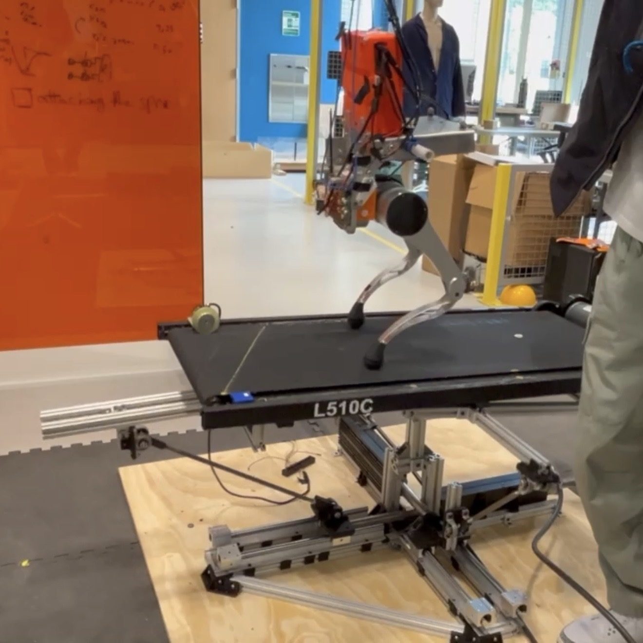
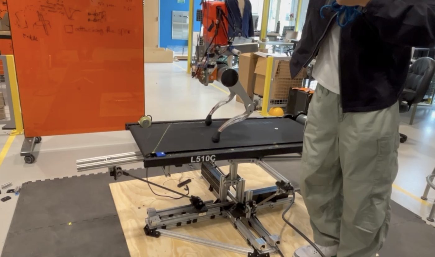
I designed and built this motion platform for the RAM (Robotics, Automation and Mechatronics) Lab at Rutgers. It holds a treadmill and can tilt it in multiple axes, and it's now being used for locomotion research in the lab. The whole project took around one semester.
Mechanism
I designed this to give researchers at the RAM lab a way to manipulate a treadmill in multiple axes without buying an expensive system. There are only a few commercially available ones, and they're 5–6 figures.
Professor Yi told me we had linear motors lying around in the lab that had gone unused for nearly a decade, so I designed the system around converting the linear motors' sliding into rotation of the platform.
The obvious way to tilt a platform is a rotary actuator on each axis, but at these loads (around 60 Nm in pitch) that means buying high-torque gearmotors for every axis, which starts to defeat the point of not buying a commercial system. Since the linear motors were already there, the problem became turning their push into rotation.
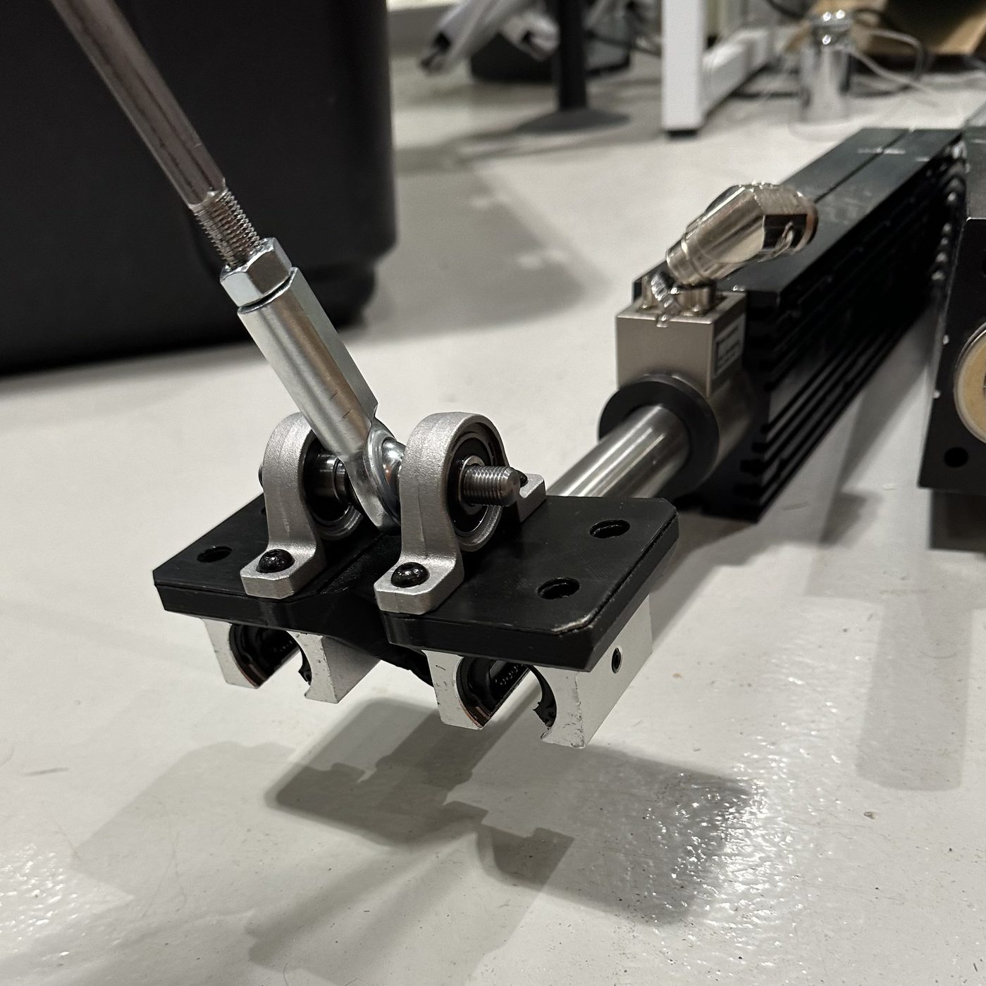
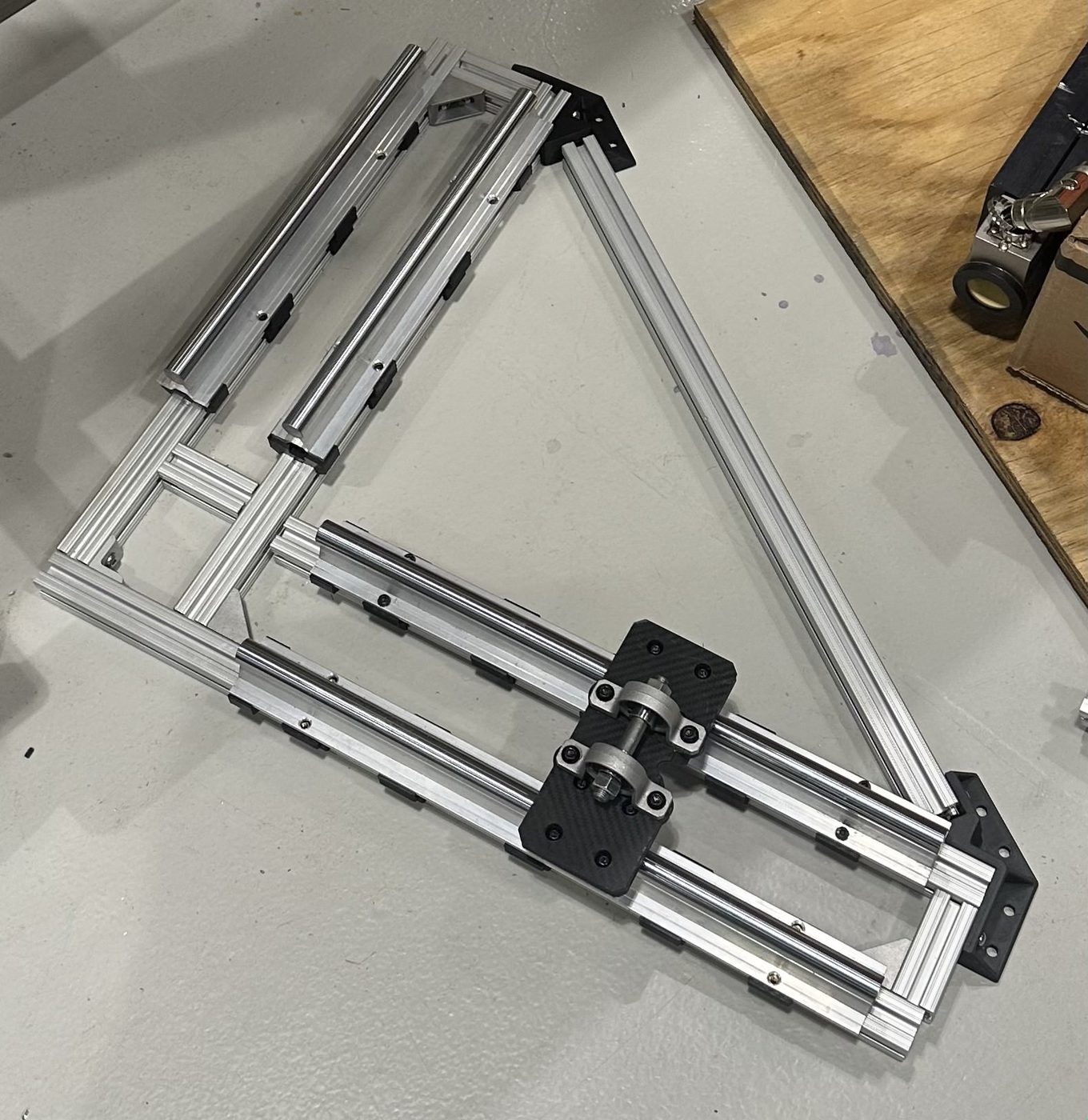
After trying a few joint configurations, I went with an offset crank-slider on each axis. The linear motor drives a carriage along its rail, a rod connects the carriage to a crank under the platform, and pushing the carriage rotates the platform about its pivot.
| This platform | Commercial gait treadmillse.g. Motek M-Gait with its pitch/sway option | |
|---|---|---|
| Moves the treadmill in | Pitch and roll | Pitch and side-to-side sway |
| Range | −25° to +5° pitch, −20° to +10° roll | Not published |
| Treadmill | A standard treadmill sits on top | Built in: instrumented dual-belt, 0–5 m/s |
| Actuators | Linear motors the lab already had, through crank-sliders | Built in |
| Cost | Reused the lab's motors | 5–6 figures |
The torque you get out of this isn't constant. If the motor pushes with force F, energy in has to equal energy out, so the torque at the platform is the force times how far the carriage moves per radian of tilt:
Where the carriage has to move a lot for a small rotation, you get a lot of torque. Near dead center, where the rod and crank line up, dx/dθ goes to zero and the motor can't turn the platform at all. The crank length, rod length and offset e set the shape of that curve, so those are the numbers I had to choose.
Simulation
The torque each axis needs comes from the load on the platform: the weight of the treadmill and whatever's walking on it, acting at a distance from the tilt axis. Before building anything, I had to make sure the linkage could beat that in both axes at every point in the workspace, so I wrote a Python sim to check it.
The sim sweeps each axis through its range and plots the carriage travel Δx(θ) next to the torque. The torque curve is just the motor force times the slope of the travel curve, which is why it drops off as the travel curve flattens toward the end of the range.
I couldn't find crank, rod and offset lengths that met the torque requirement everywhere by adjusting them one at a time, because each one moves the whole curve. So I wrote an optimizer that varies all of the geometry at once and finds the shortest link and offset lengths that still generate the required torque at every possible position.
The optimizer works inside hard limits. Some come from the hardware: the linear motors' stroke and force, and how much room there is under the platform for the links to swing. Others come from the research the platform is for: the tilt range each axis has to reach (about −25° to +5° in pitch and −20° to +10° in roll) and how fast it has to get there. A geometry that breaks any of them is thrown out, however good its torque curve looks.
The sim's output didn't stop at the design. It maps every carriage position to a platform angle, and every angle to the torque available there. The control code uses that map to turn a commanded tilt into carriage positions for each motor, and the torque map tells it where in the range it can move quickly and where it has to back off.
Build
After validating the design I did parts selection and CAD, then prototyping and iteration, and eventually assembly and testing.
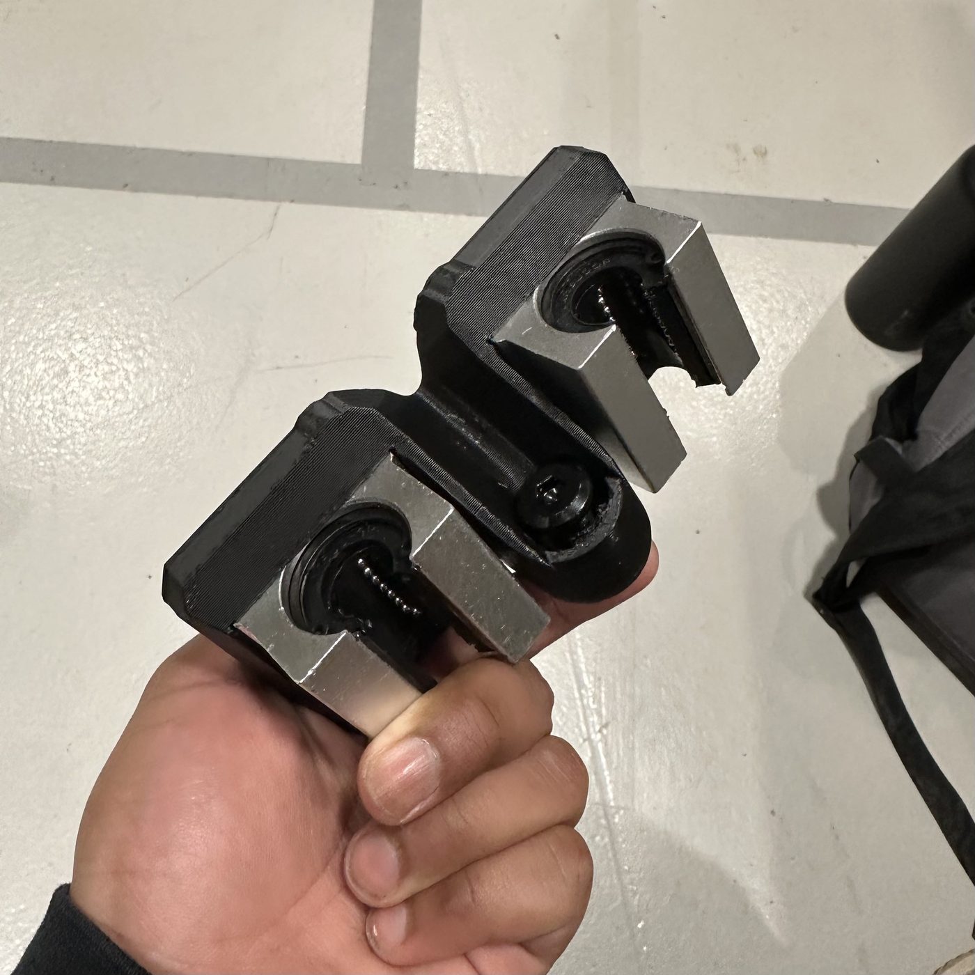
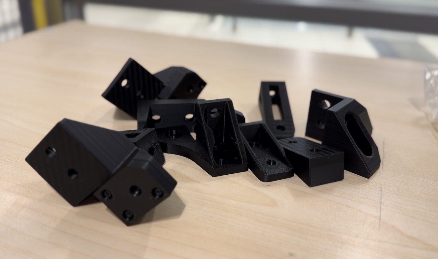
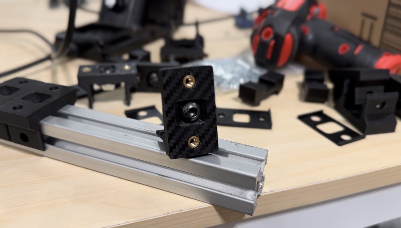
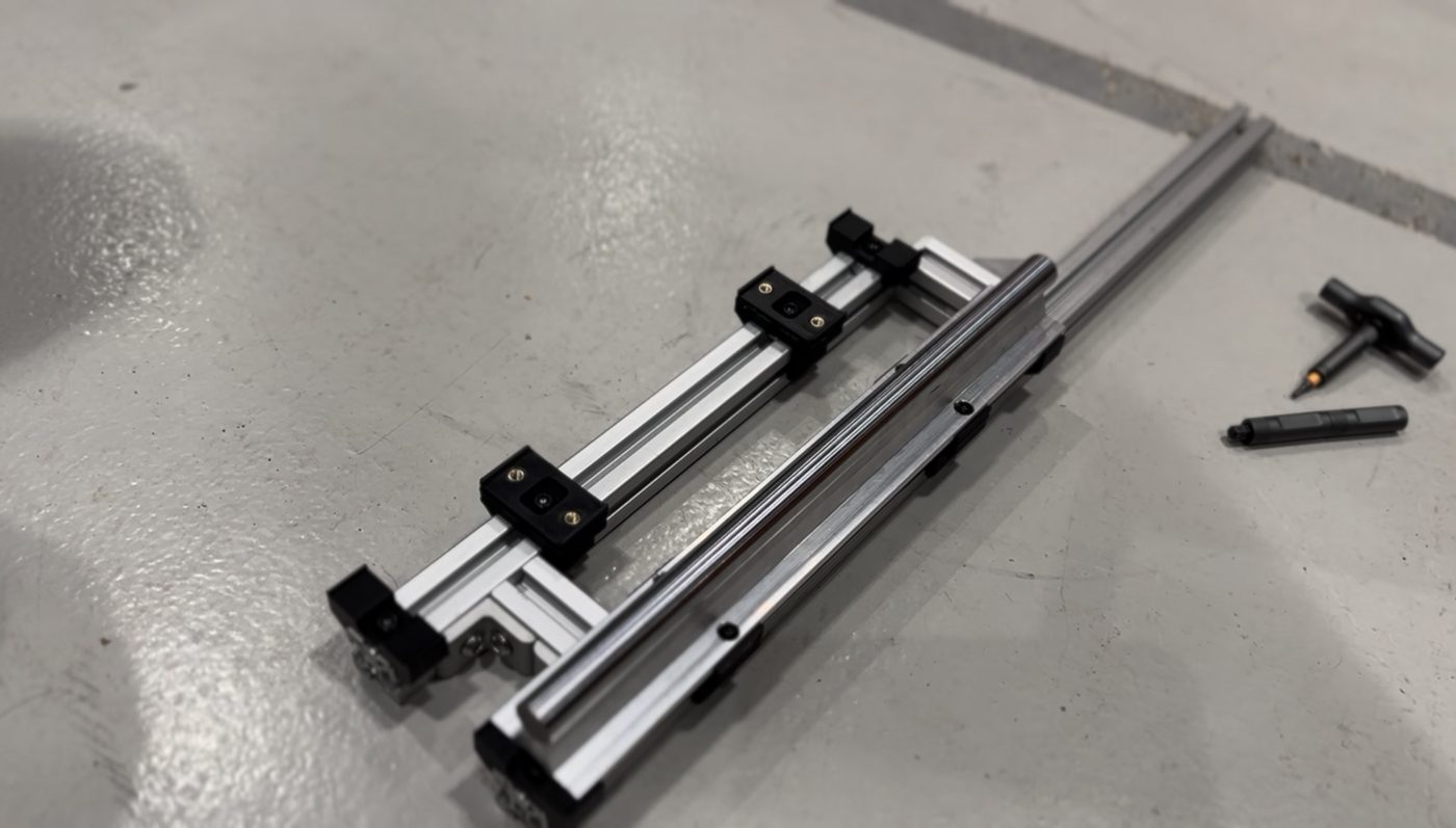
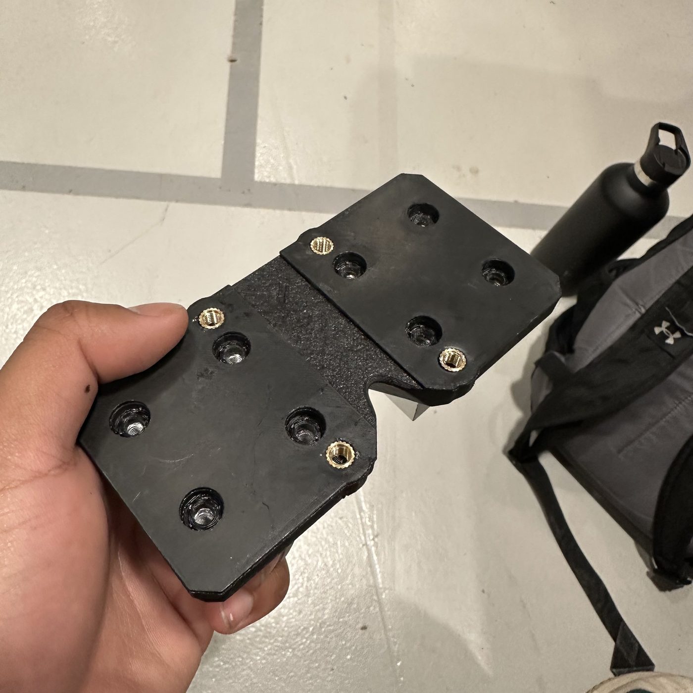
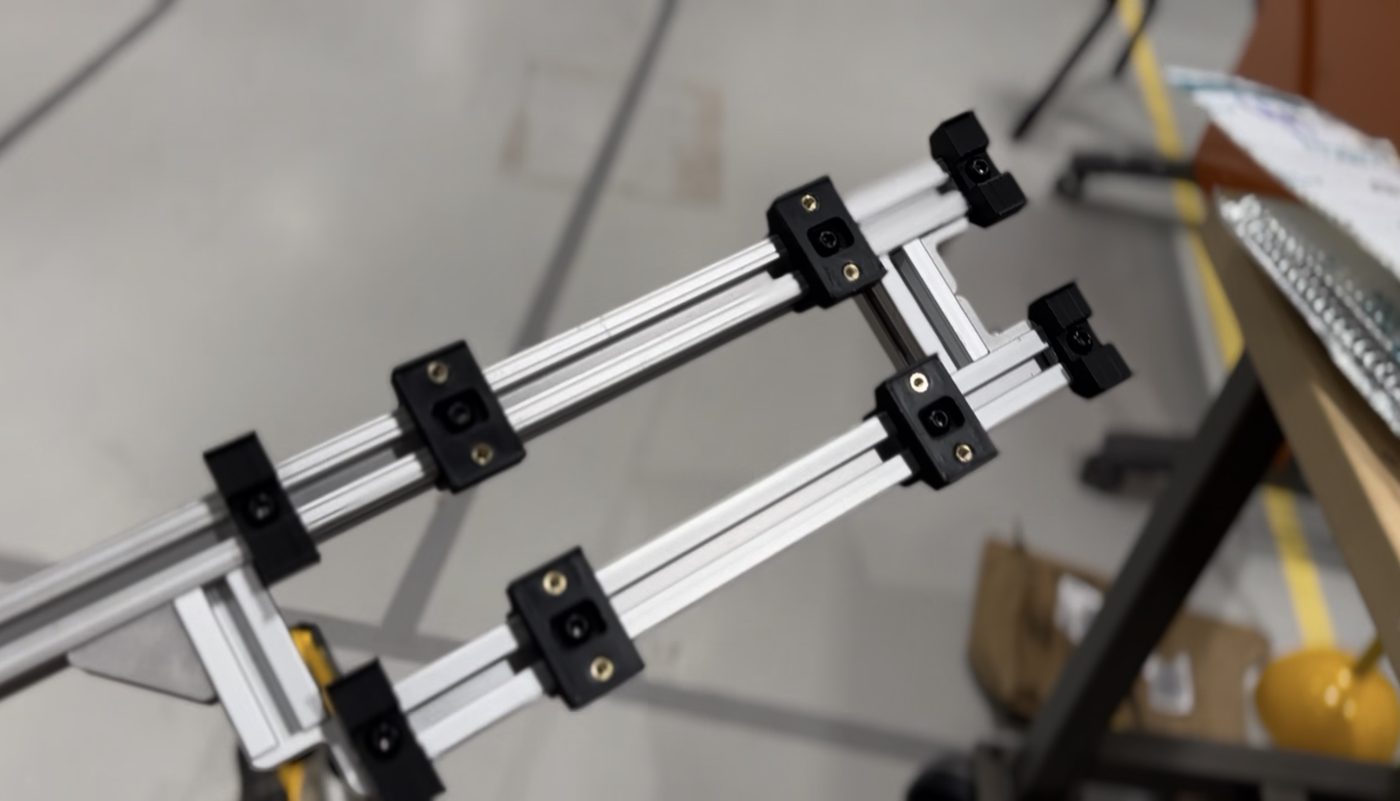
The base is aluminium extrusion joined with 3D printed brackets, with heat-set inserts pressed into the prints to take the bolts. Each linear motor got a printed carriage plate riding on bearing blocks, with the pivot for its rod on top. Before it went into use, I tested it with weights on the platform to check its torque and speed.
In use
It's now being used for research in the lab, including locomotion papers.