STEERING ROBOT
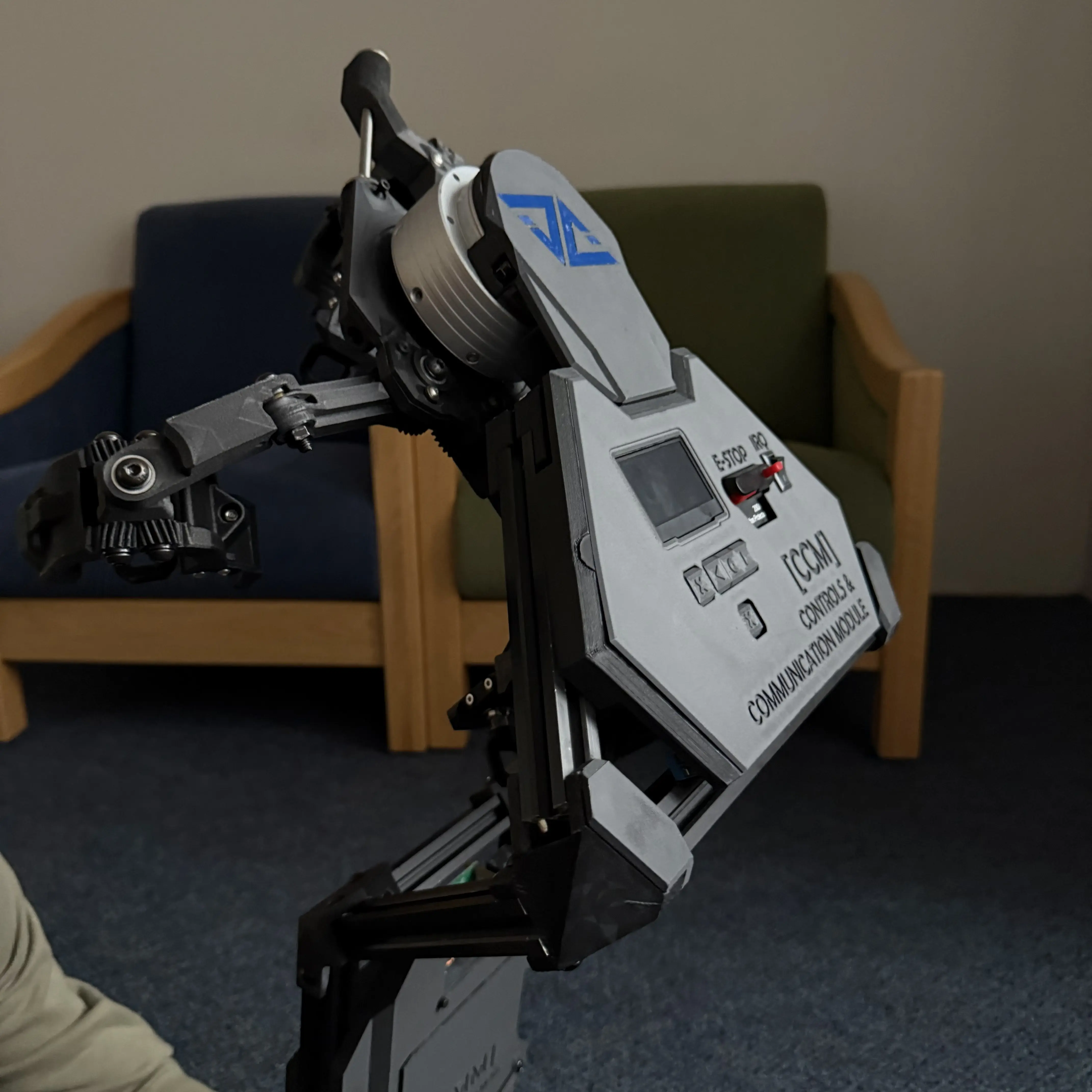
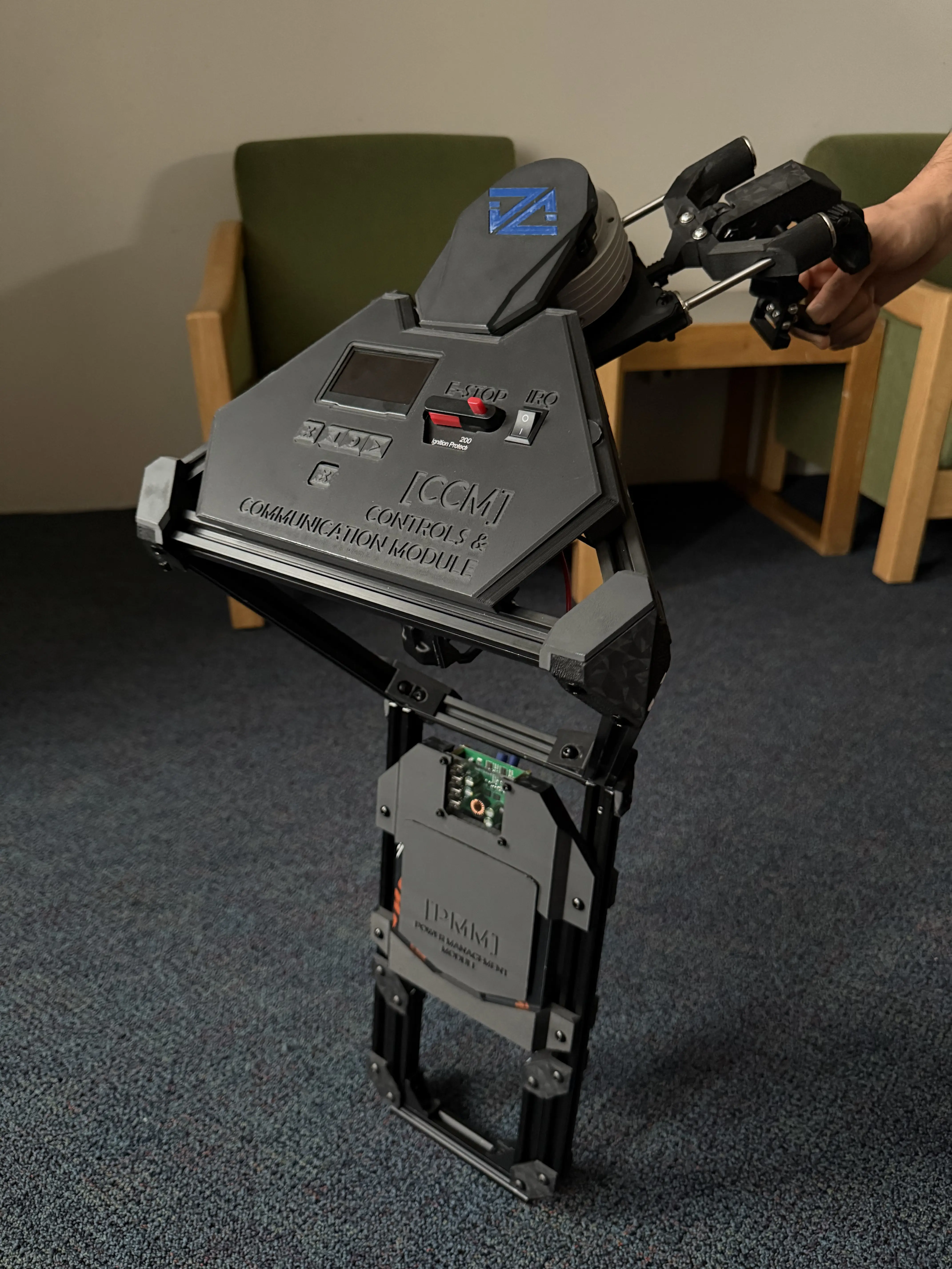
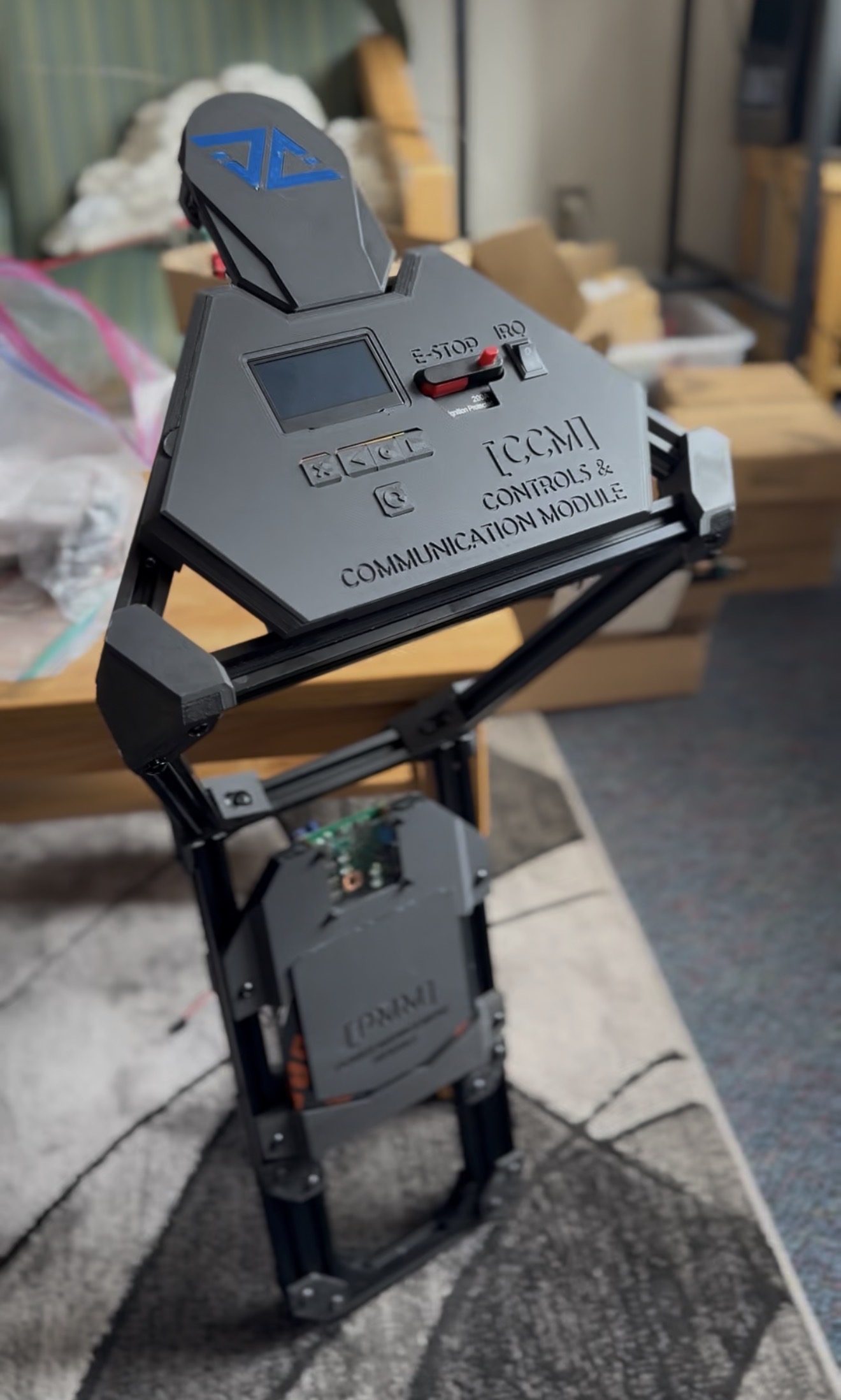
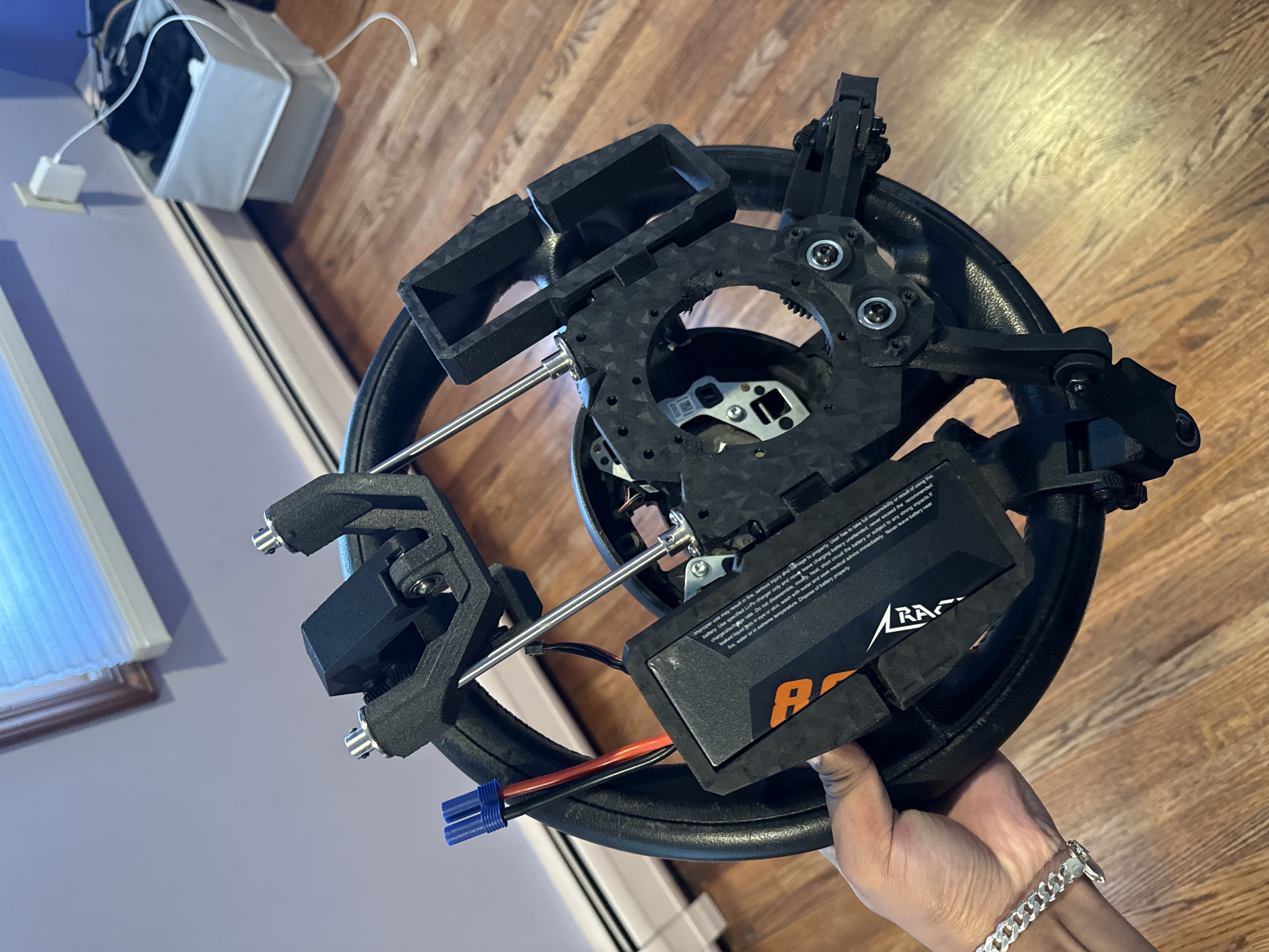
A steering robot that attaches to the steering wheel of any car in about a minute, without modifying it, and steers it for Gen Auto AI's autonomous driving stack. I'm a founding engineer at Gen Auto AI and owned this robot from concept to working build. Below is the engineering behind it.
Autonomous drifting for collision avoidance
Gen Auto is building an autonomous driving stack to drift ordinary commercial cars at the level of a professional stunt driver. The first maneuver is the J-turn, used for collision avoidance. To run on any car, the stack needs a way to turn that car's steering wheel. That is the steering robot.
A small selection from tens of papers.
steering angle
Vehicle state: wheel speeds, throttle/brake, steering angle
Perception: LiDAR, camera, GNSS/INS
perception → compute → steering
Goals & requirements
- Fit any car and any steering wheel with the same parts.
- Never modify, damage, or permanently fasten to the car or its steering wheel.
- Attach and come off by hand in about a minute.
- Work without steering wheel dimensions, since manufacturers don't publish them.
- Let the safety driver steer and take back control at any time.
- Cost a fraction of existing steering robots, which run $20–100k.
System simplification
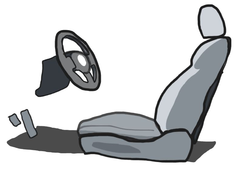
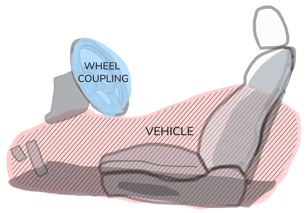
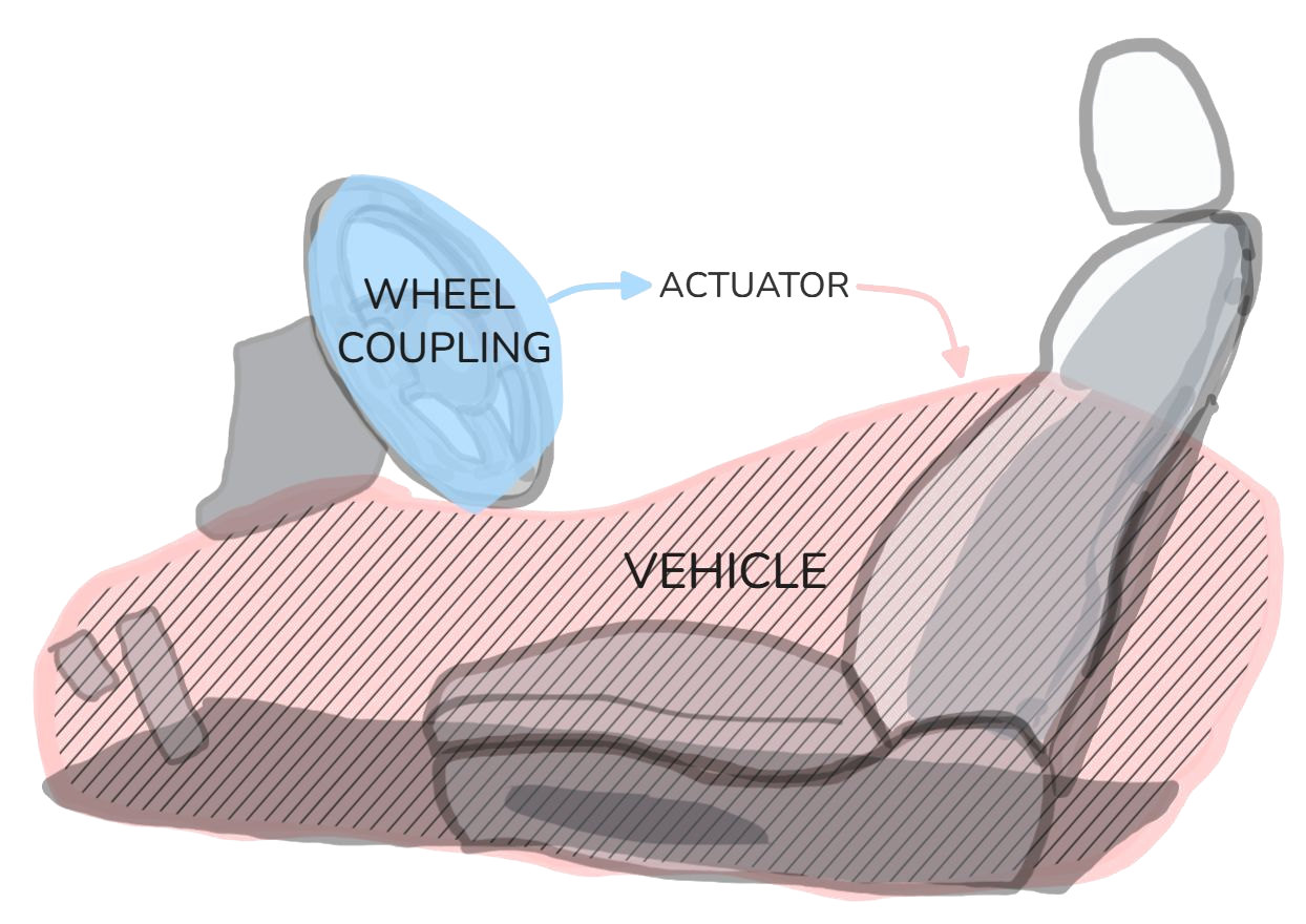
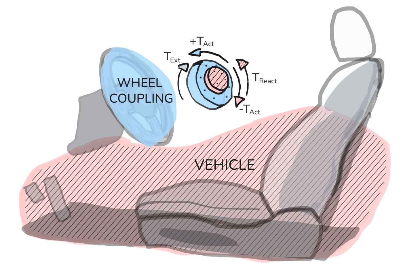
The robot only has to apply torque to the steering wheel. So the car splits into two bodies: the steering wheel, and everything else (the vehicle). An actuator between them turns the wheel by pushing against the vehicle.
That leaves three parts to design: the actuator, the wheel coupling, and the connection to the vehicle that takes the reaction torque.
Actuator selection
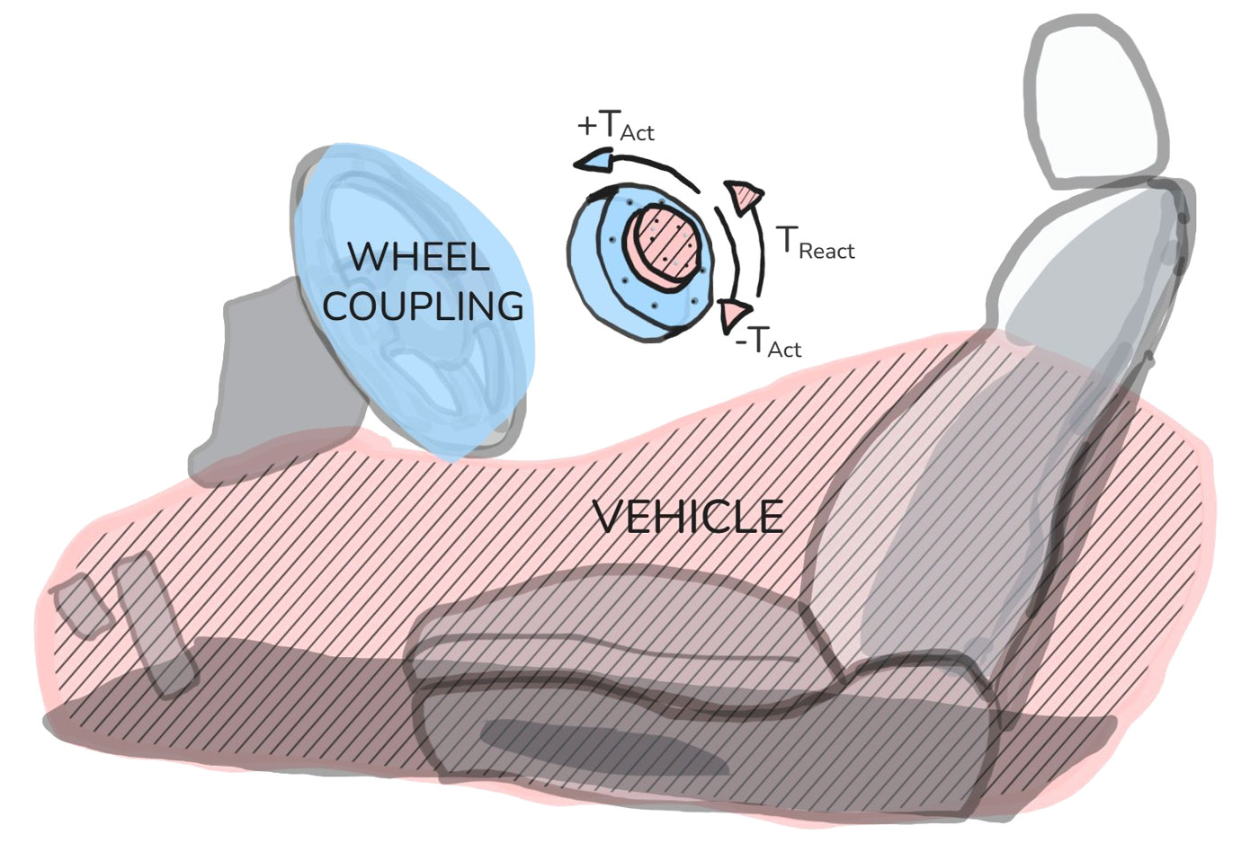
The actuator applies torque Tact to the wheel coupling. The same torque acts on the actuator housing in the opposite direction (−Tact), and the vehicle has to hold it as the reaction torque Treact.
Text is the external torque on the steering wheel from the tires and the driver, which the motor measures itself.
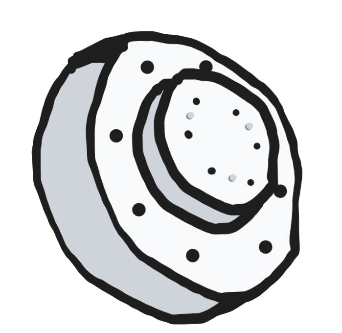
Unconventionally, I chose a brushless QDD (quasi-direct drive) actuator, the kind usually found in legged robots.
Cheetah-style motor
- High torque density BLDC (small)
- Dual encoders and a good FOC controller (precise)
- Torque control mode (integrated torque sensing)
- 1 Mbit/s CAN control
| Motor | Steering | Headroom | |
|---|---|---|---|
| Cont. torque | 8 N·m | 1–5 N·m | 1.6× |
| Peak torque | 24 N·m | 15 N·m | 1.6× |
| Speed | 40 rad/s | 13–15 rad/s | 2.7× |
| Accuracy | < 0.15° | minimal |
This means none of the torque or force sensing hardware that every other solution needs. The gearing is low enough that the motor is backdrivable, so it senses the load on the steering wheel proprioceptively, through its own back-EMF and current. It also has a zero-torque mode that cancels the actuator's back-driving friction: the driver can use the steering wheel as though the robot weren't there, and the robot can record a maneuver as it's driven and play it back autonomously.
Recording and playback
The torque sensing is what makes this possible: in zero-torque mode the robot follows the wheel while someone drives, records the maneuver, then plays it back by itself. These are the first eight seconds of the same U-turn, recorded and played back.
Attaching to any steering wheel
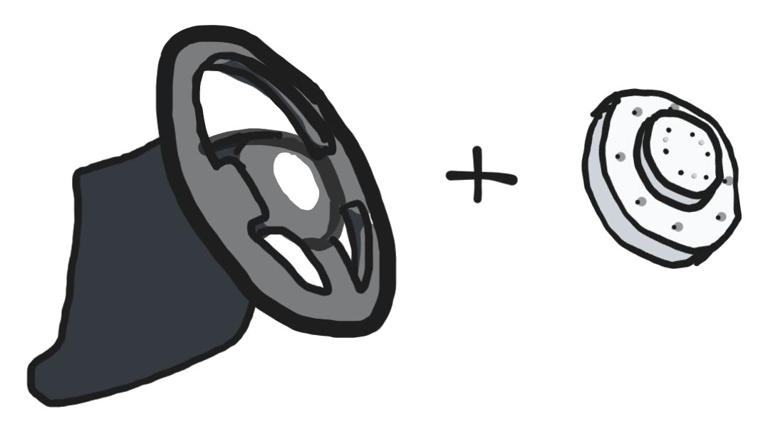
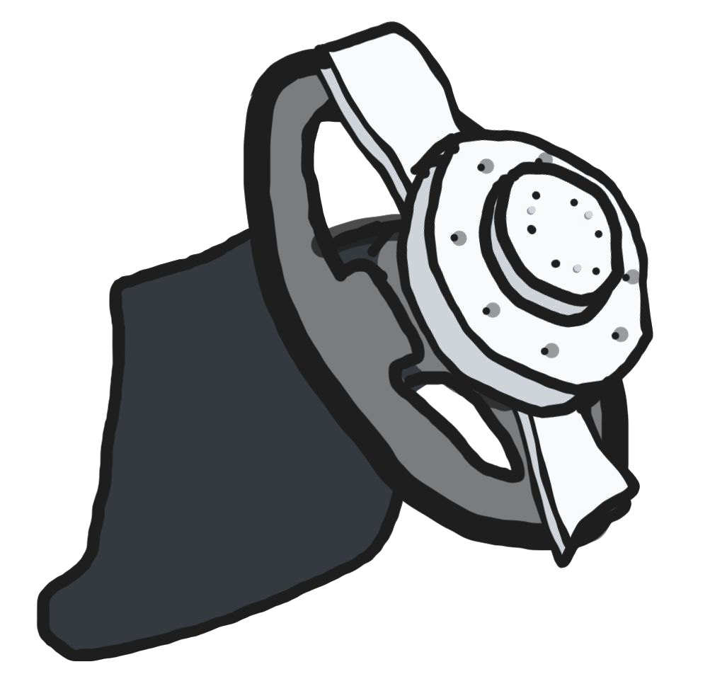
The wheel coupling holds the actuator on the steering wheel. It has to fit any steering wheel, put the motor on the wheel's axis of rotation, and lock rigidly, using only clamps operated by hand. No tools, no permanent fasteners, and no damage to the steering wheel.
Each subsection below is one way steering wheels differ from car to car, and the joint that handles it.
Clamping to any wheel.
The size and shape of the steering wheel's cross-section change along the wheel, and suppliers don't release wheel geometry, so clamps can't be designed to match it. The clamps still need a robust fastened and unfastened state on every wheel.
Solution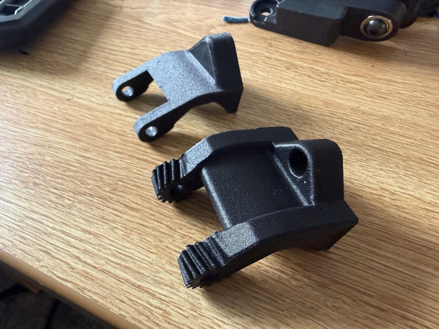 Early vs. final iteration
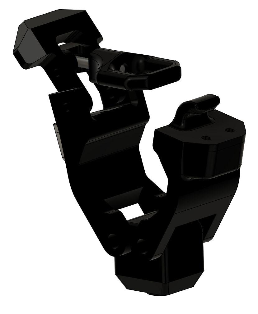 My clamp design.
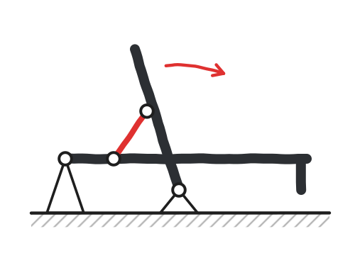 The four-bar linkage.
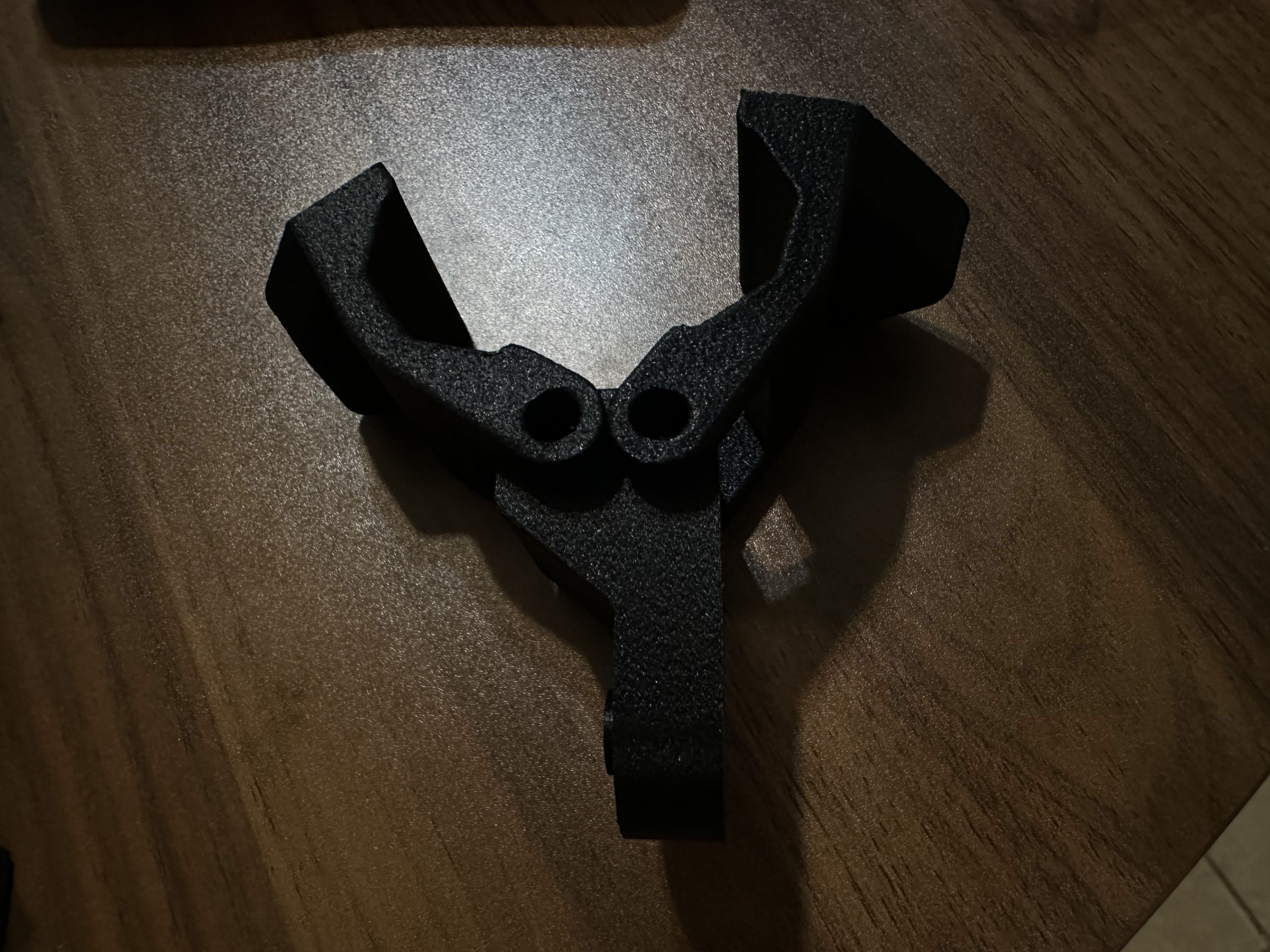
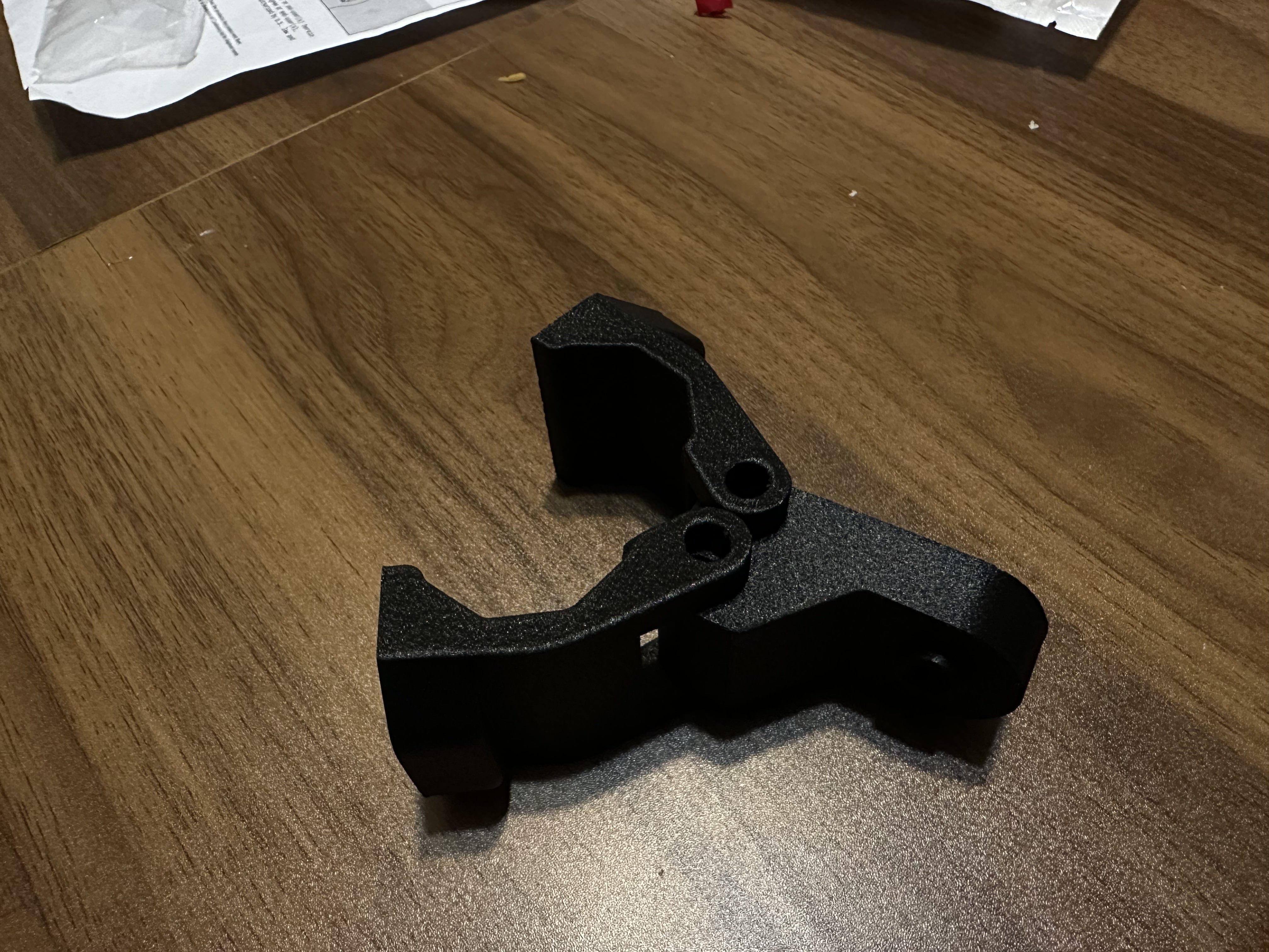
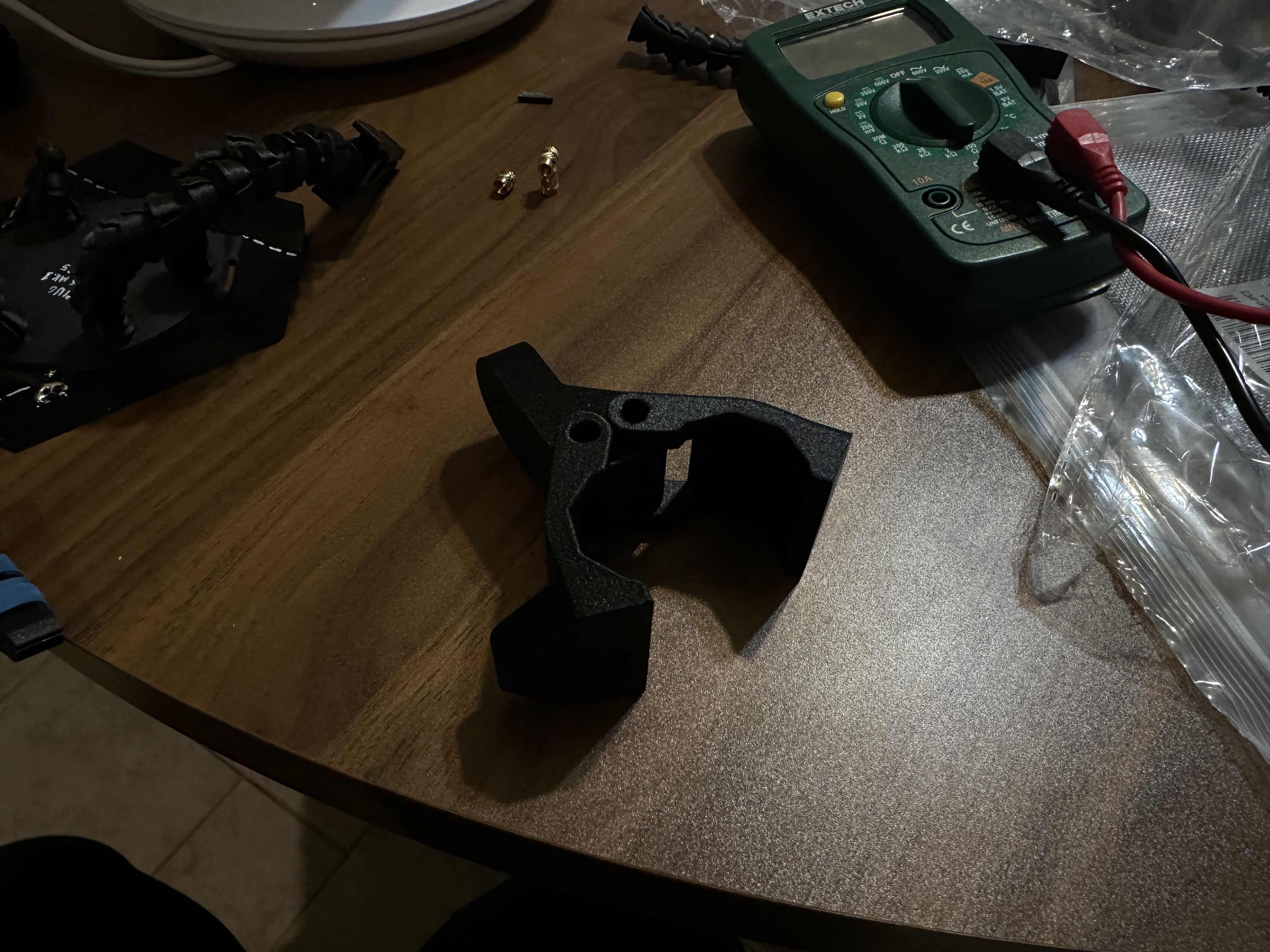
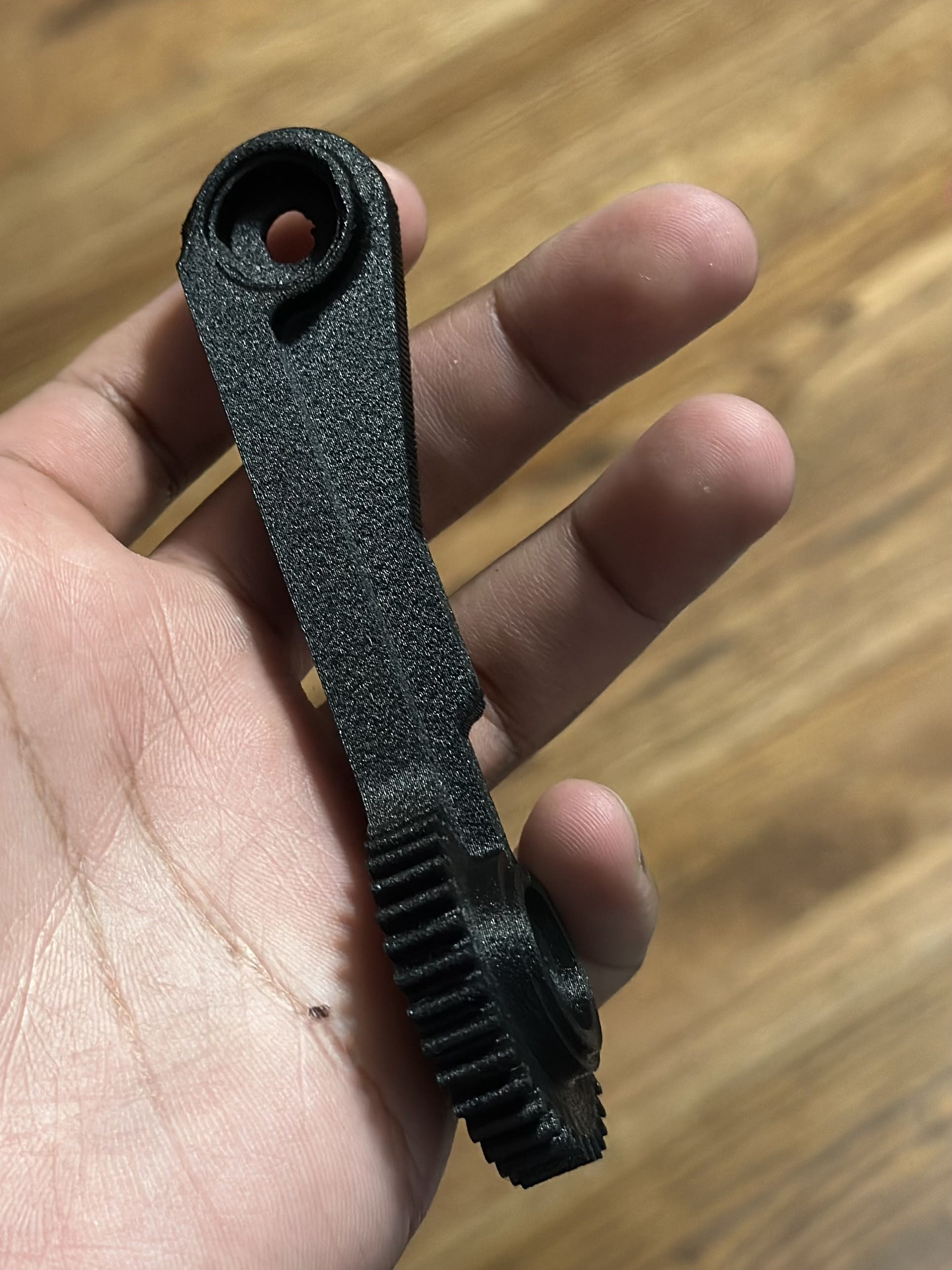
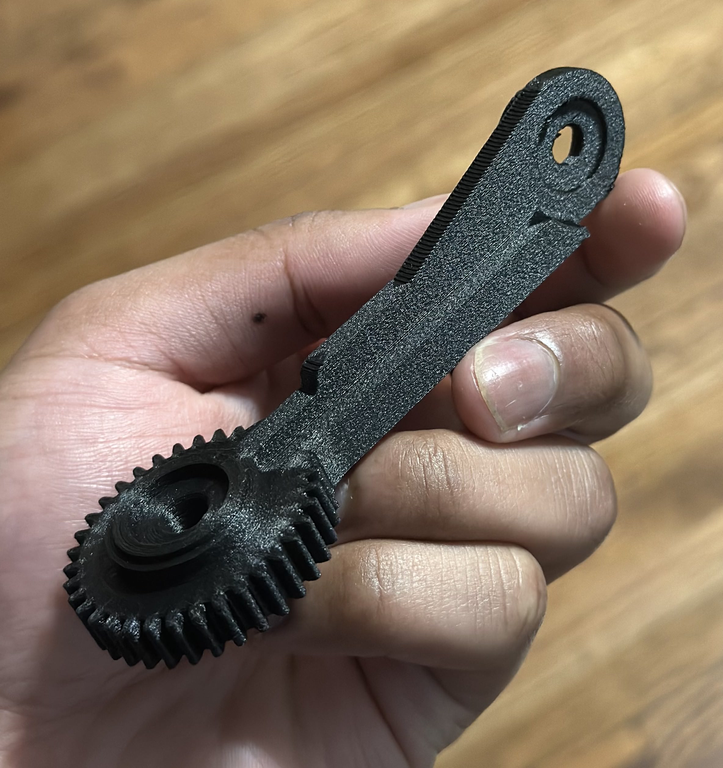
Each clamp is a toggle clamp: a four-bar linkage that locks once the handle pushes the link just past center. It works across a range of sizes and shapes, and it's quick to open and close by hand. Changing the link lengths tunes the clamping force and how much the clamp deforms. They're printed in carbon fiber nylon.
Handling all wheel diameters.
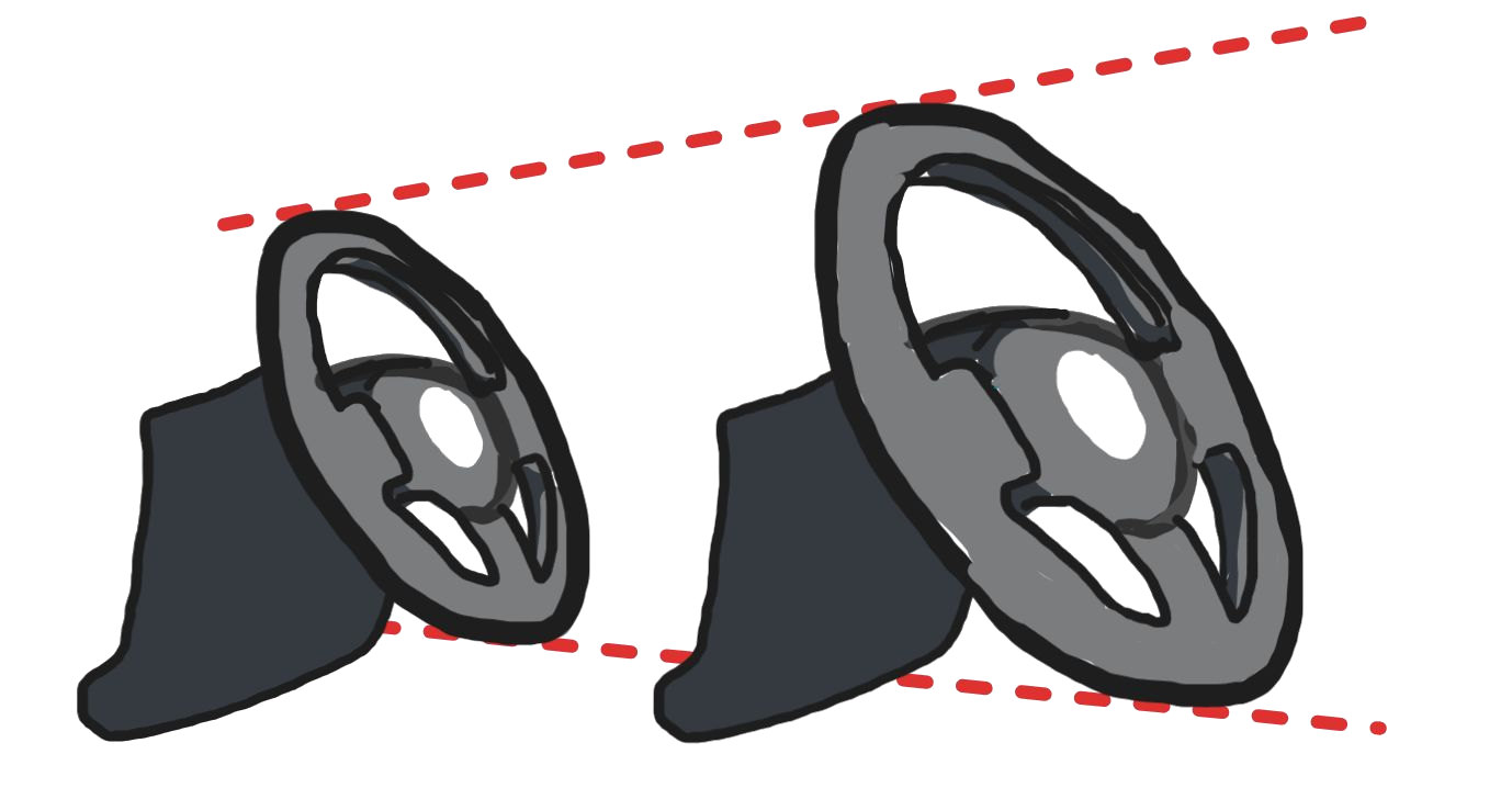
Steering wheel diameters range from 14″ to 19″ on average, and many common wheels are smaller or larger.
Solution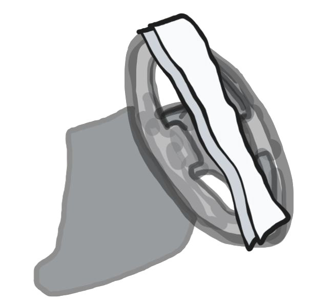
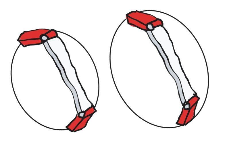
A revolute joint before each clamping point. The bar spans any diameter without moving the center point.
Adapting to any shape.
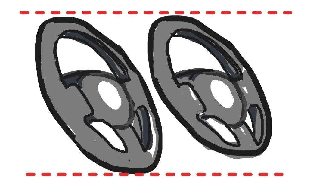
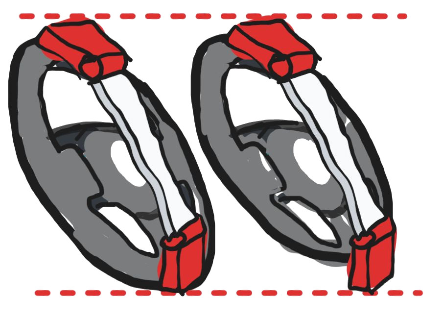
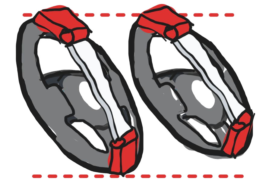
With one bar and a revolute joint at each end, the bar only stays parallel to the wheel face if the wheel is round. Steering wheels aren't circles: if the top-to-bottom length differs from the width, the joint angles differ and the bar tilts.
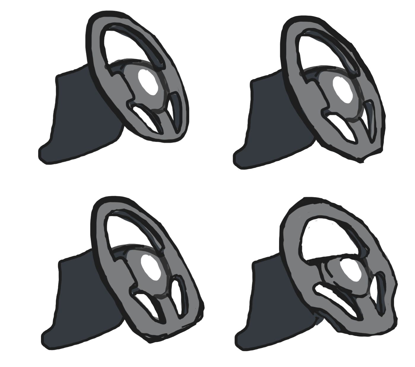
The bottom of the wheel can't be a clamping point anyway: there's a spoke there, which blocks the toggle clamp from wrapping around the wheel. And the spoke layout is different on every steering wheel.

Use two arms at the bottom instead of one, and let them swing out to the sides. They pivot about points below the wheel's center, not at it, so the arc each arm's clamp sweeps (red) isn't concentric with the rim. It has to cross the rim, at one point along the arc.
The top arm and the arcs are the same on every wheel. Only the shape of the wheel changes, and that decides where along its arc each clamp meets it.

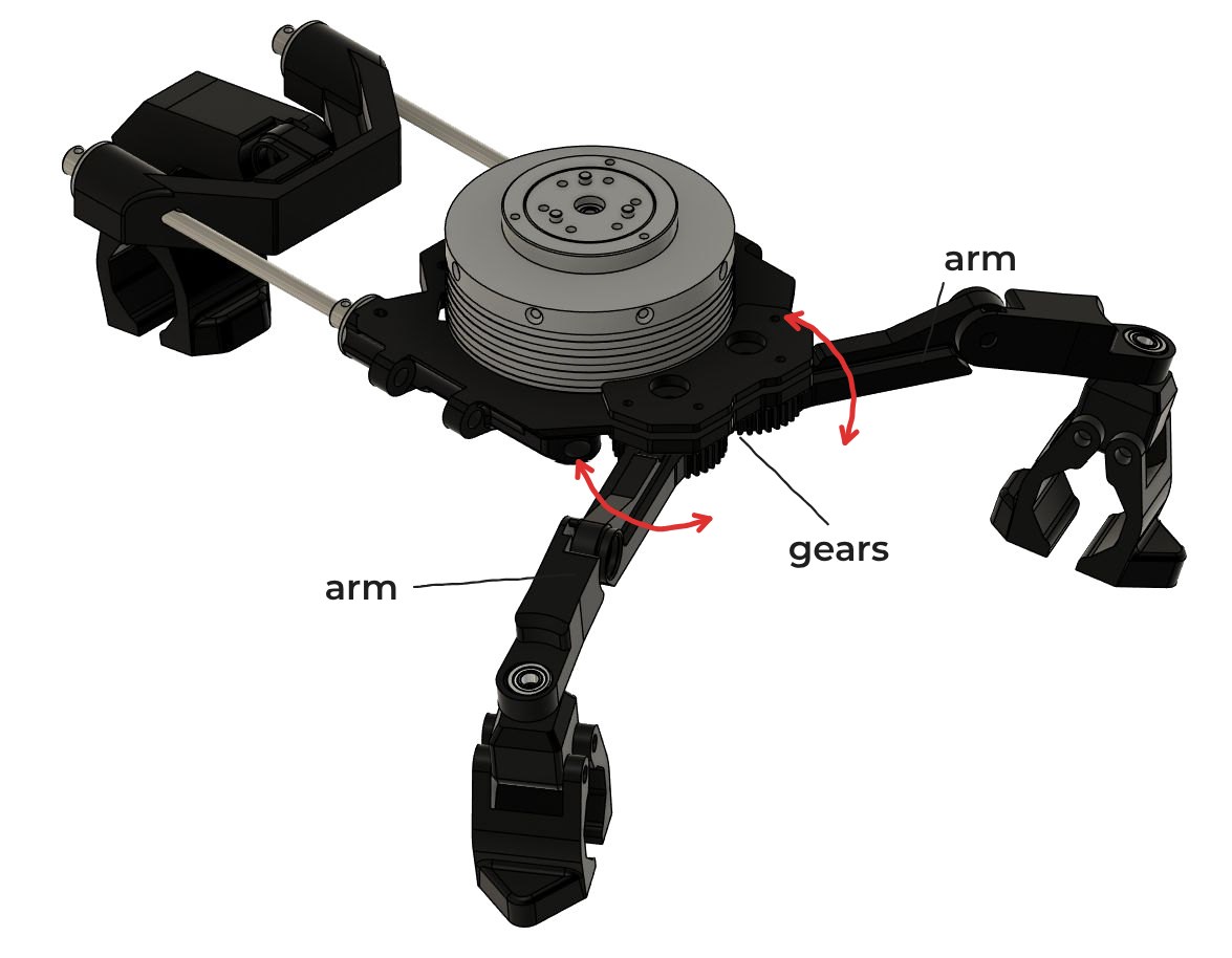
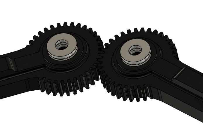
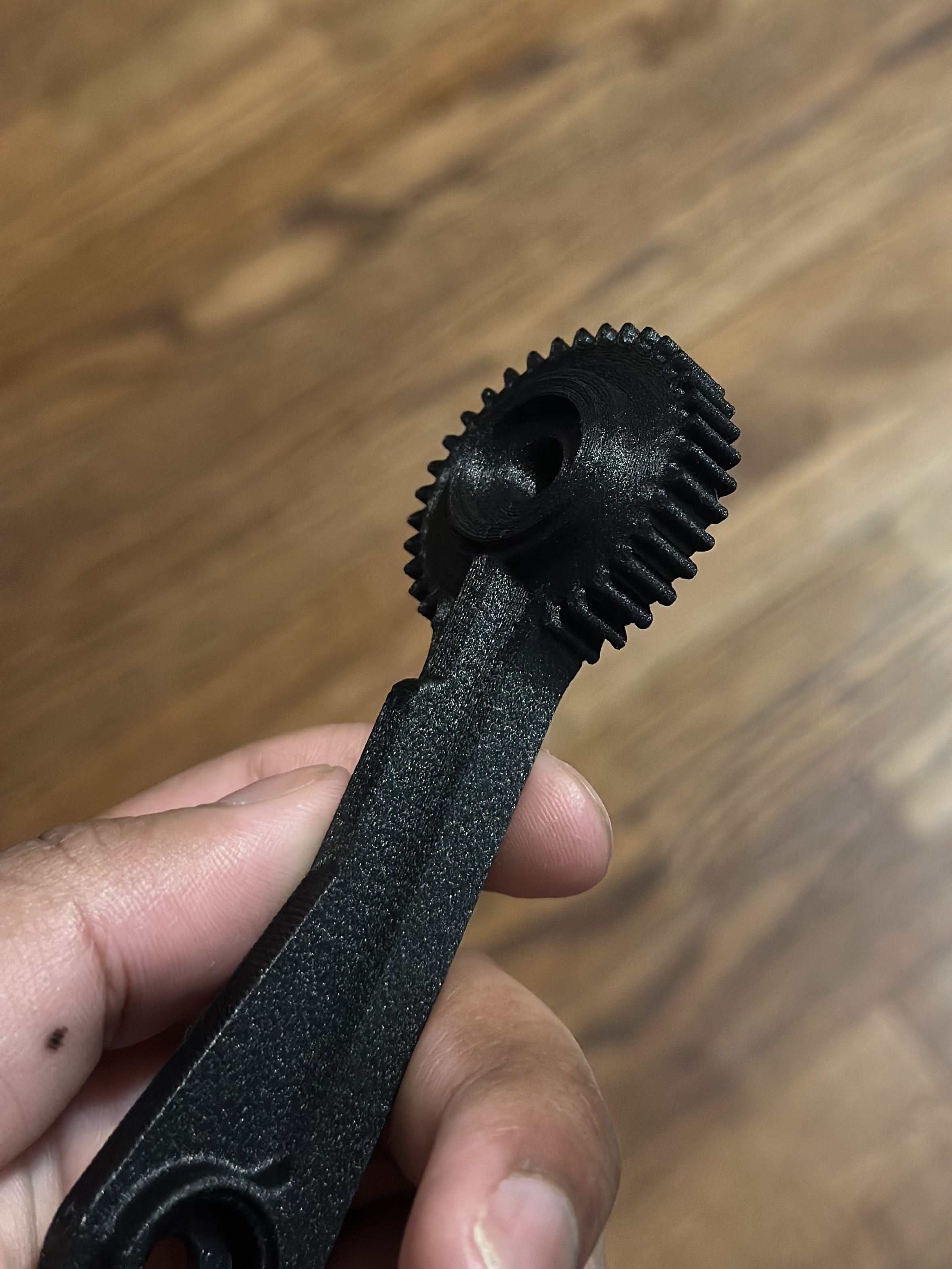
Coupling the two arms mechanically with gears keeps them symmetric: they always counter-rotate by the same angle.
Wheels aren't concentric.
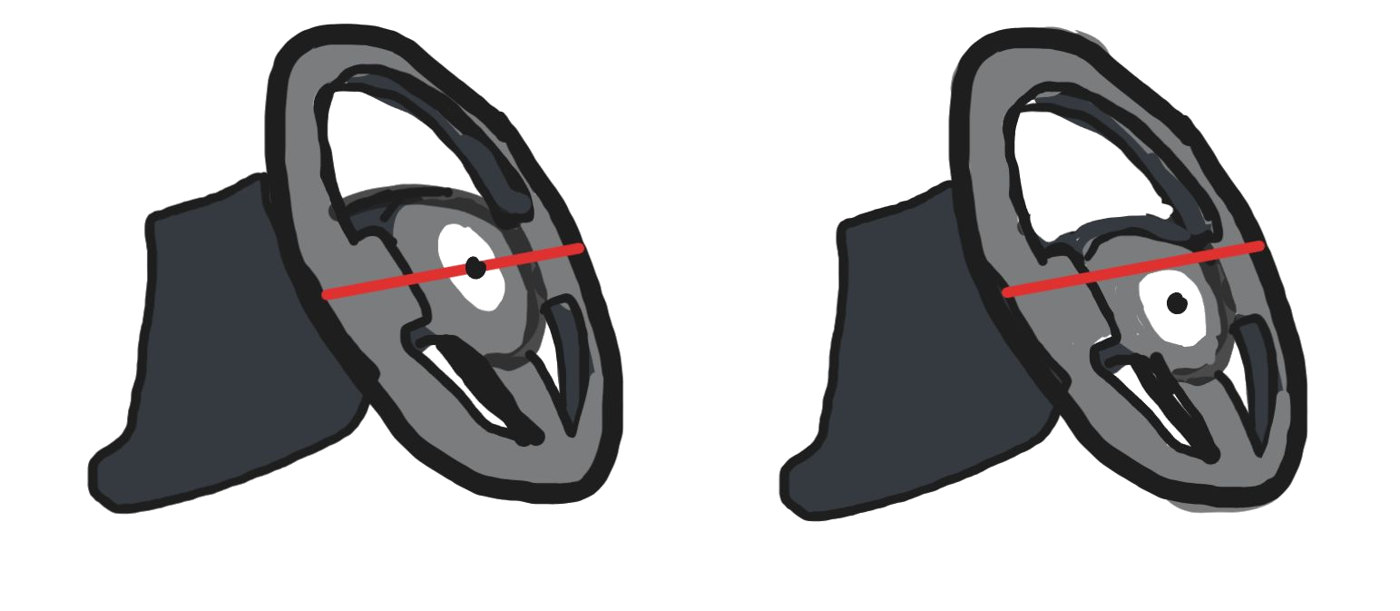
Steering wheels almost always have an offset between their geometric center and their axis of rotation, to improve turning ease. The motor has to sit on the axis of rotation, not the center.
Solution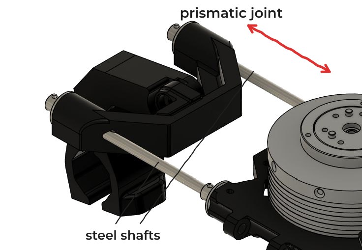
A prismatic joint along the vertical axis: parallel steel shafts sliding through shaft mounts embedded in the CF nylon print. It is set once per car, so it doesn't need to be as smooth as the other joints.
Full assembly.
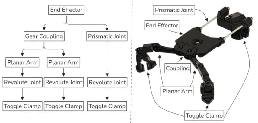
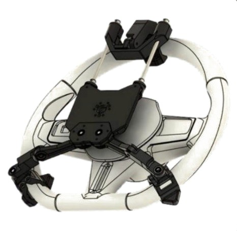
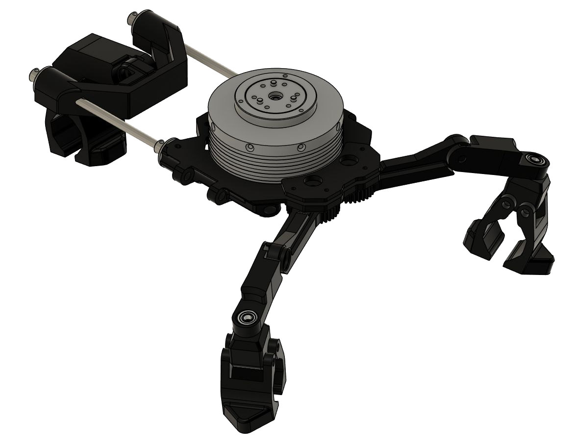
The joints adjust to the steering wheel, then lock in place once all three toggle clamps are closed, constraining motion in every degree of freedom. The motor ends up concentric with the axis of rotation and parallel to the wheel, on any car.
Frame-based actuation
For the actuator to turn the steering wheel, its housing has to be held still. Every N·m it applies to the wheel acts on the housing in the opposite direction, and something has to take that reaction torque.
Existing steering robots take it with a frame mounted to the car.
Industry solutions
Fixed to the windshield
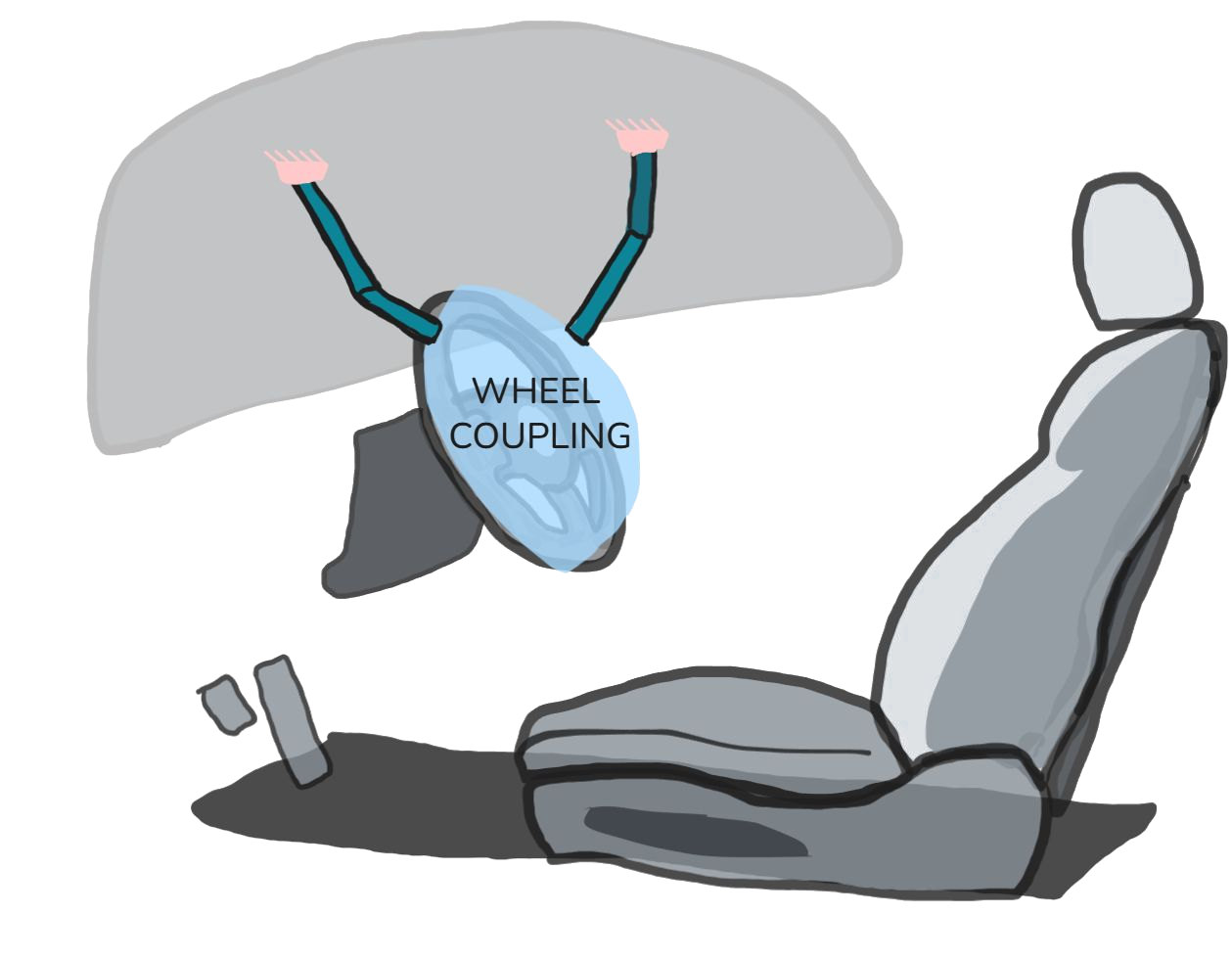
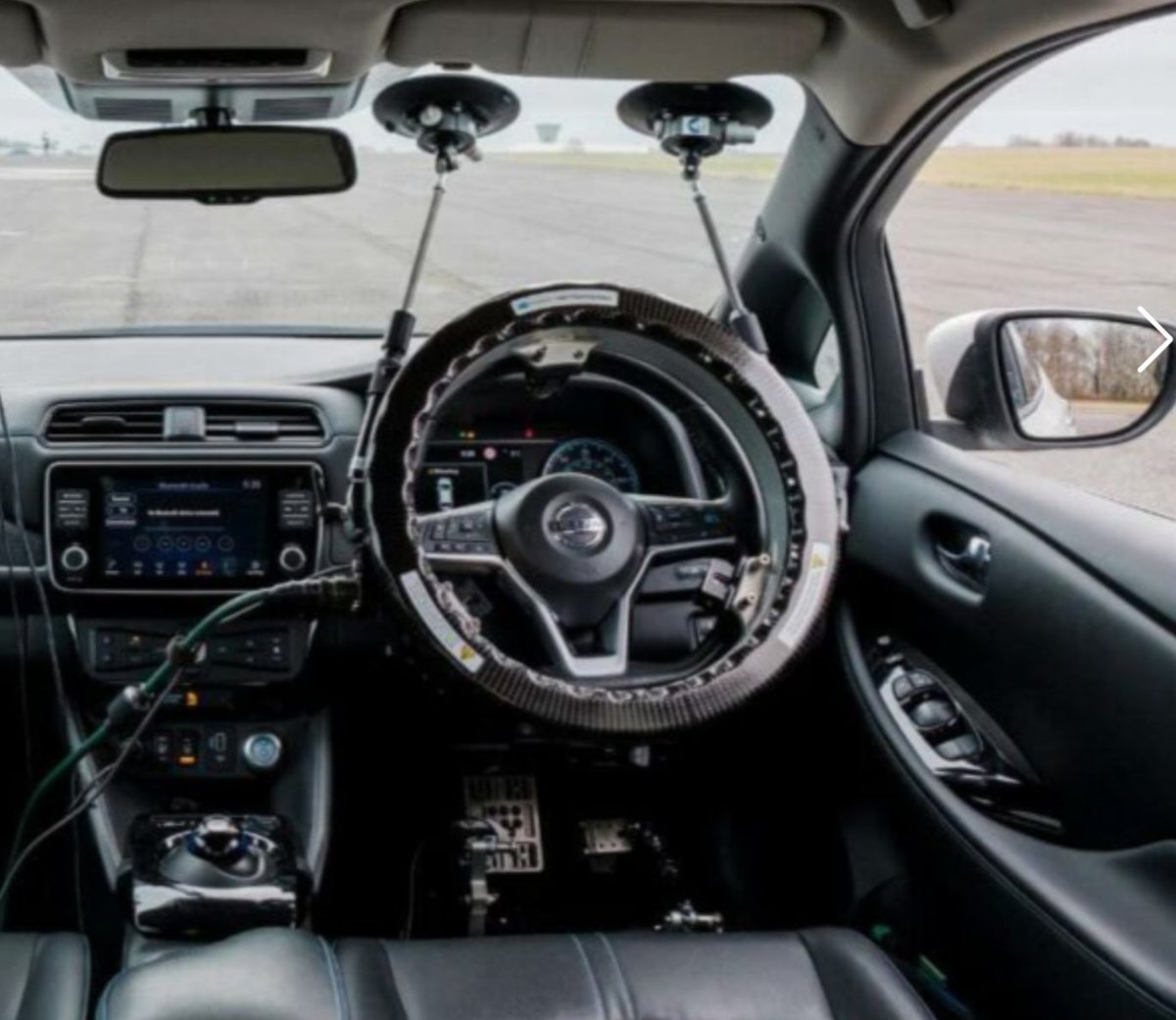
A frame attached to the windshield with suction cups holds the actuator in front of the steering wheel. It sits in the driver's field of view, and the torque it can take is limited by the suction cups.
Cost: $20,000–100,000+
Fixed to the floor
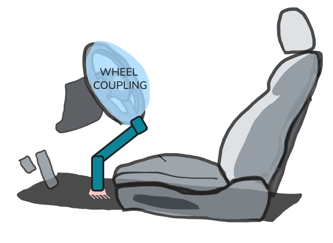
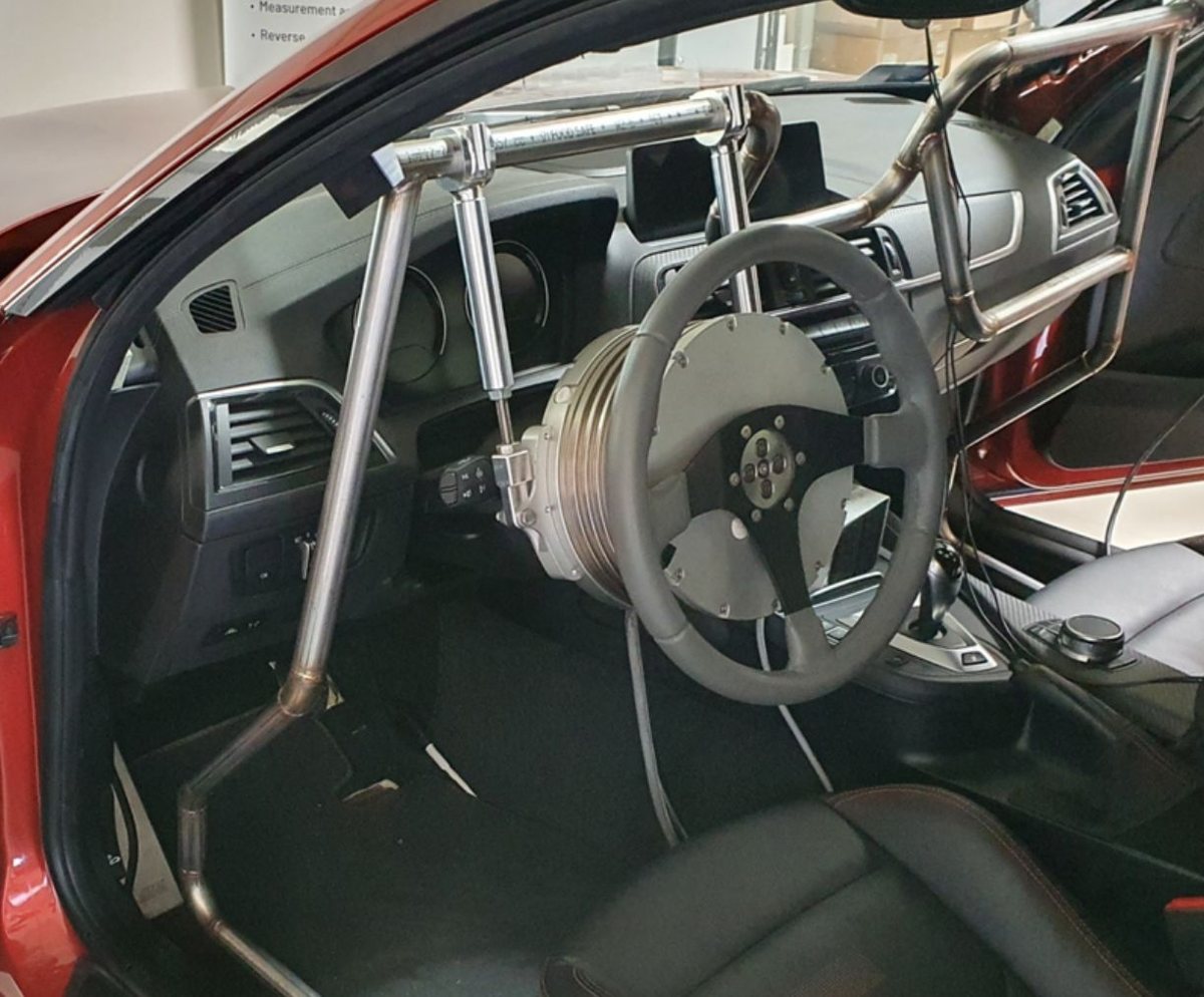
A rigid frame from the floor holds the actuator. It can take high torque, but it is large, has to be fitted to each car, and usually needs permanent modifications.
Cost: $20,000–100,000+
This robot: < $500 in parts
The floor as a constraint
A frame has to fit any car too. The steering column angle and the wheel height are different in every car, and they are measured relative to a floor whose shape, height and angle are also different in every car.
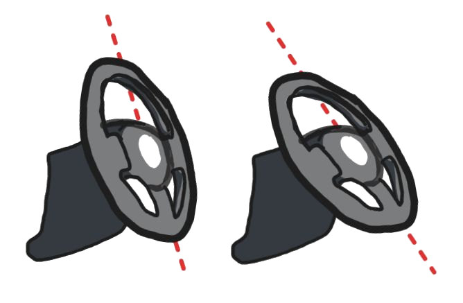
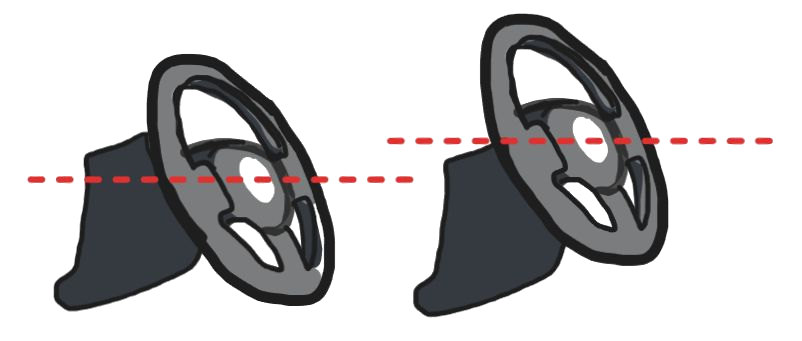
Instead of a frame fixed to the car, the arm uses the floor as a constraint. It extends from the actuator until it meets the floor, without fastening to anything, and once extended it stops the actuator housing from moving in any direction.
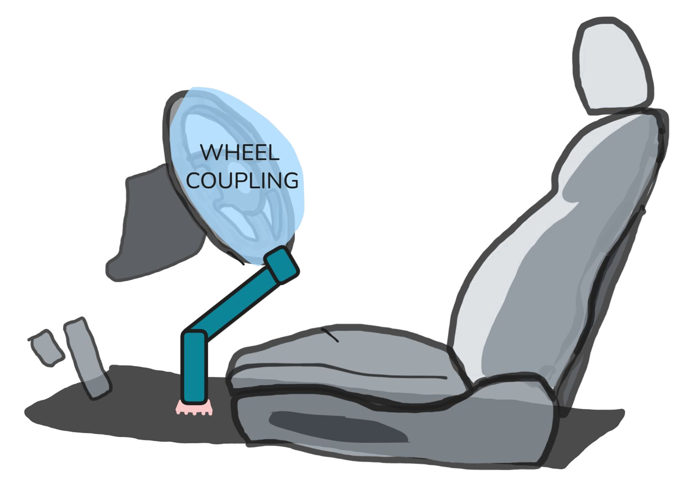
Because the motor senses the steering torque itself, the frame needs no torque sensors. Industry solutions have to put them in their frames.
The frame also carries the battery and the CCM (controls and communication module). Its screen shows sensor data, the steering angle, telemetry and connection status, and its buttons take control, trigger the emergency stop, and power cycle the robot.
Self-contained actuation basis for patent
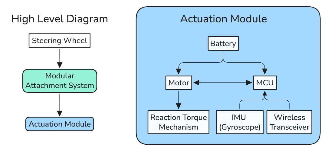
Removing the frame entirely would make the robot much simpler to use. It wouldn't have to adapt to each car's interior, it would be smaller, and with a battery it would be wireless, with no power cables running through the cabin. The whole robot would be the part on the steering wheel.
Self-contained actuation should be impossible. Without pushing against the car, the only thing left to push against is a mass carried by the robot, and no mass that fits within a steering wheel's envelope can produce enough reaction torque.
Reaction wheel
The usual way to make torque without a fixed reference is a reaction wheel: accelerate a flywheel, and the housing gets the opposite torque. But the torque only lasts while the flywheel is accelerating. Once it reaches the motor's maximum speed, the motor can't produce any more (saturation). A flywheel's inertia also goes with r², so the small radius behind a steering wheel hurts it badly.
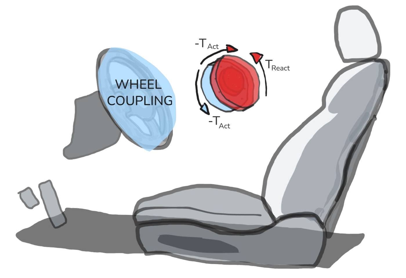
Even with a 50 lb steel disc, the motor couldn't hold a 3 N·m turn for more than 5.5 seconds.
So the robot can't push against the car, and it can't keep accelerating a mass. How can it produce a torque at all?
My idea
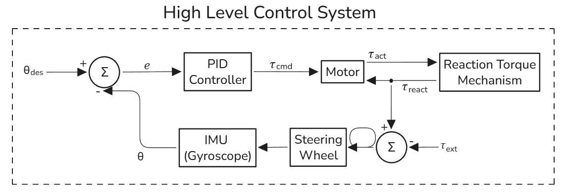
Push against gravity instead, with a pendulum. Holding an offset mass up produces a sustained torque without accelerating anything: under a steering load, the pendulum tilts until gravity balances the torque. It never saturates, and it fits behind the steering wheel.
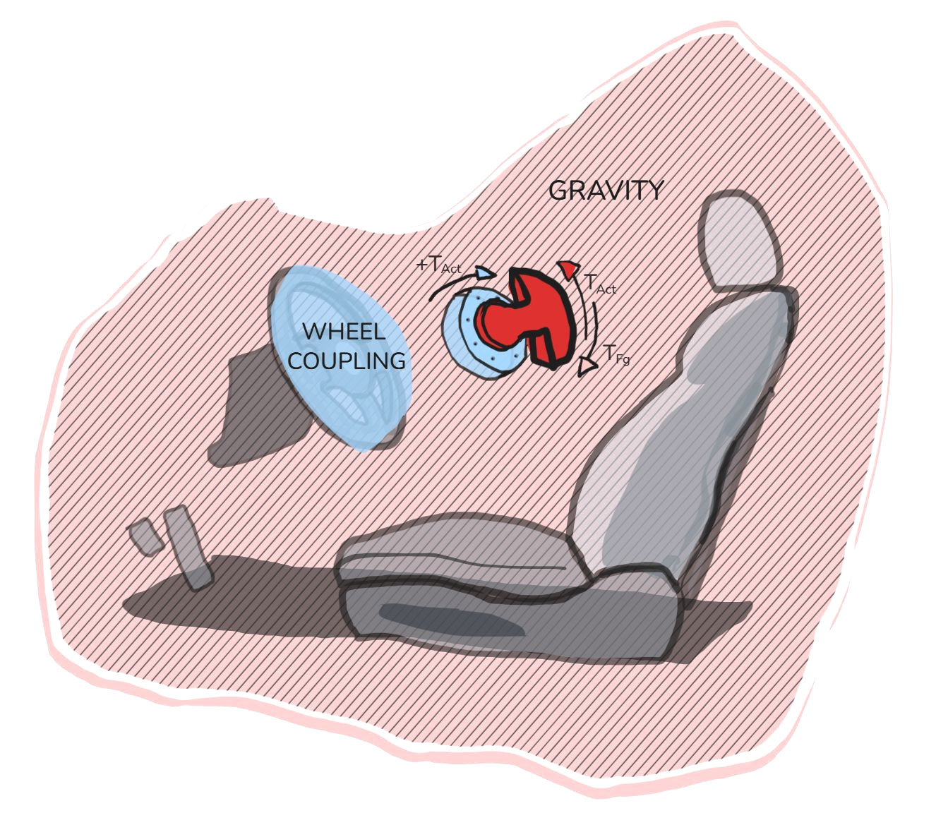
Gravity is a free ~10× multiplier (g ≈ 9.8 m/s²) on the torque a mass can make, and it never runs out. The pendulum's torque also goes with r, not r², so a small radius matters much less: the opposite of the reaction wheel. Holding this pendulum at 90° takes 19.45 N·m, more than the 15 N·m peak steering torque, so in practice it never gets there.
Outcome
- It works.
- Commercialization grant funding.
- Patent process and protection through TechAdvance at Rutgers.
- Interest from universities and ADAS testing subcontractors.
Perception testbed
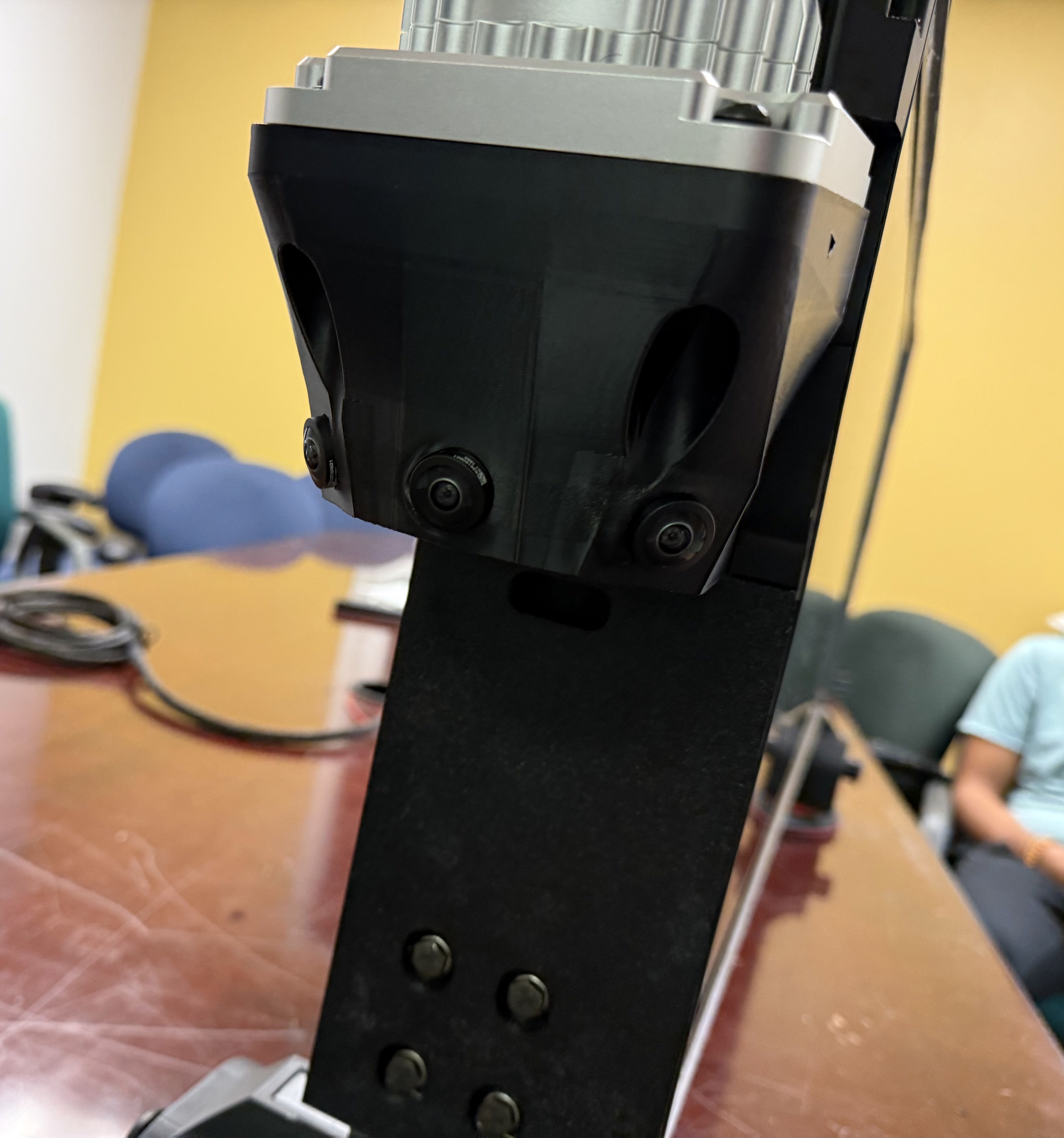
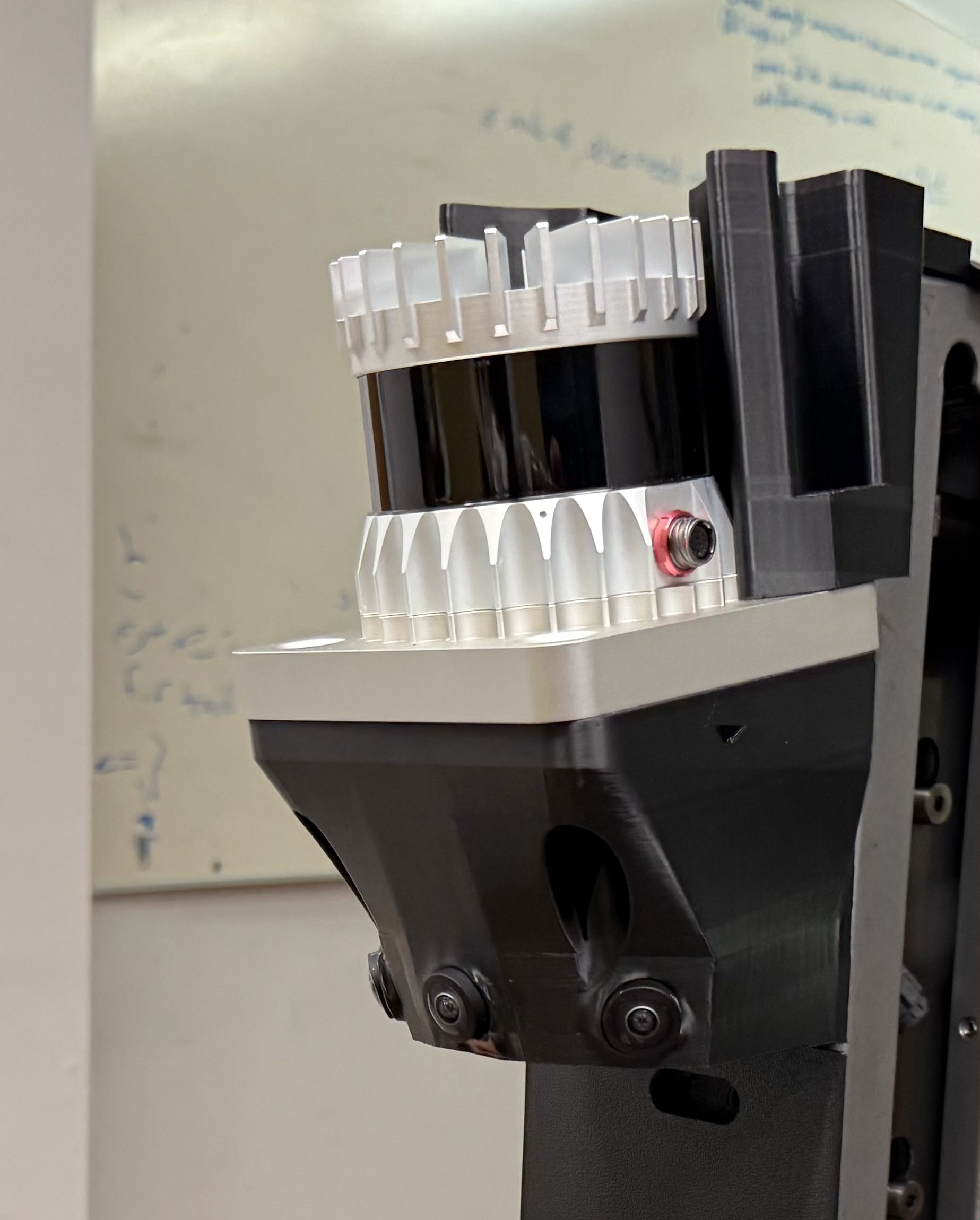
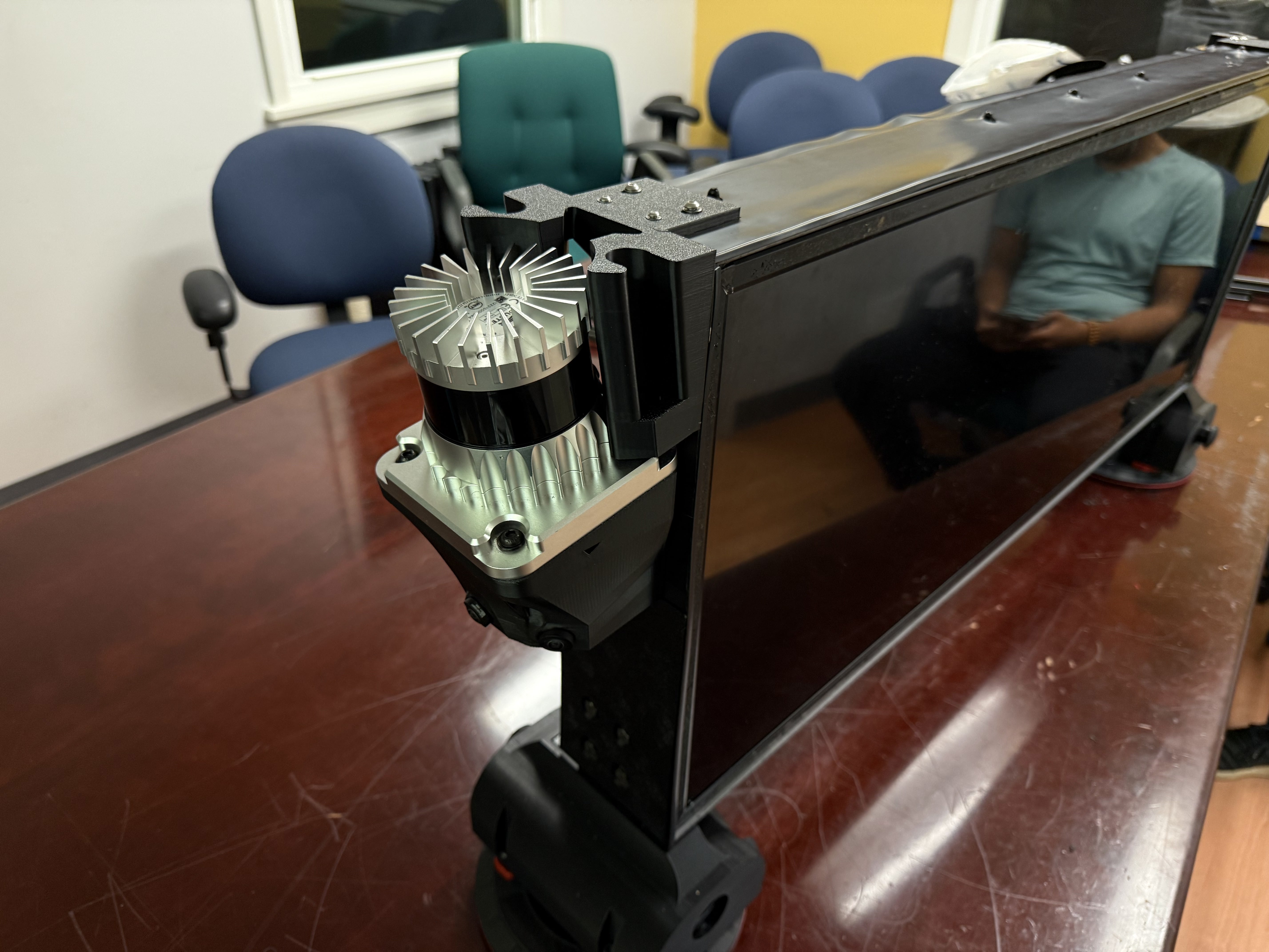
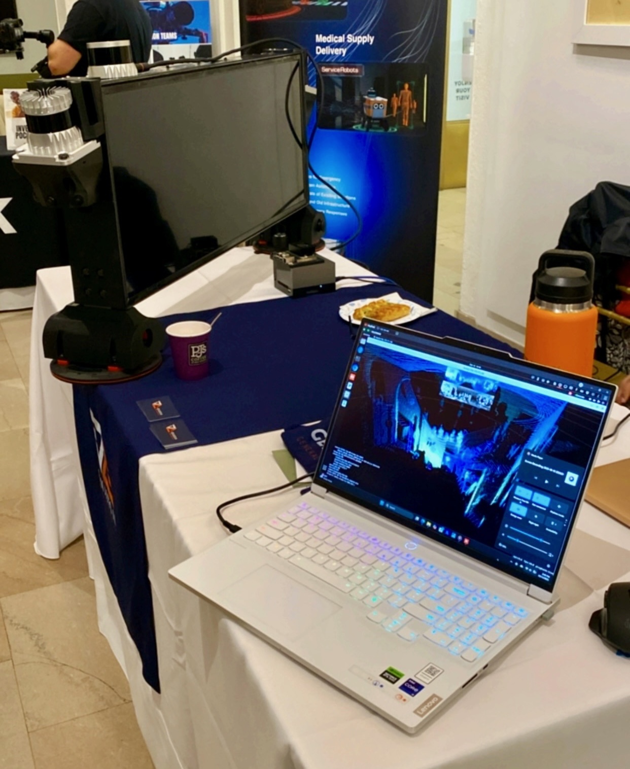
Alongside the steering robot, I worked on the perception testbed that feeds it: LiDAR, cameras, and an IMU-GPS module on the vehicle, running through ROS2 on an NVIDIA AGX Orin.